jeffreyrtk@gmail.com

Hi, I'm Jeffrey, the funder of toknavgnss.com, I've been running a factory in China that makes GNSS RTK for 8 years now, and the purpose of this article is to share with you the knowledge related GNSS from a Chinese supplier's perspective.

TOKNAV 1a3f47bf68f65704832db732d45c8272
TOKNAV TCA920 GNSS antenna for CORS reference station projects

GNSS Antenna Selection Guide for RTK, CORS and Monitoring

Antenna Selection GNSS Antenna Selection Guide for RTK, CORS and Monitoring The GNSS antenna is a critical part of RTK rover, base station, CORS, VRS and deformation monitoring projects. Use this guide to compare signal support, installation environment, multipath risk, mounting, cable length and receiver compatibility. Request antenna support View GNSS antennas Author: TOKNAV GNSS Solution Team Reviewed by: TOKNAV Product and Field Application Team Last Updated: July 2026 Download the GNSS Antenna PDF Checklist Get a printable antenna selection checklist for receiver compatibility, signal support, mounting, multipath risk, cable planning and fixed-station installation. Name Company Email Country Project note Website Send me the PDF checklist By submitting, you agree that TOKNAV can contact you about this resource and related project support. A receiver can only work with the signal quality it receives. In open field RTK, the antenna choice affects setup stability and repeatability. In CORS, VRS and deformation monitoring projects, antenna installation can affect long-term data quality, multipath behavior and maintenance risk. This guide helps buyers compare antennas for projects using TOKNAV GNSS receivers, CORS receivers such as NET660i, base station workflows and reference station antennas such as TCA920. 1. Match the Antenna to the Application Application Antenna priority Related page RTK rover surveying Portable installation, stable signal reception, compatibility with receiver workflow. GNSS Receiver Local RTK base station Clear sky view, stable mount, cable plan and signal reliability for the project area. VRS vs RTK Base Station CORS or VRS station Permanent mounting, multipath suppression, weather exposure, grounding and maintenance access. CORS Station Checklist Deformation monitoring Stable installation, repeatable signal environment, protected cable routing and reliable data continuity. Monitoring Guide 2. Check Signal, Mounting and Multipath Conditions Signal requirements Confirm receiver model and supported constellations/frequencies. Confirm whether the project needs RTK, CORS, VRS, monitoring or mixed use. Check whether future receiver upgrades should be supported. Installation environment Open sky visibility and possible obstructions. Nearby metal, walls, water, machinery or reflective surfaces. Wind, rain, dust, cable exposure and maintenance access. Cable and accessory plan Cable length, connector type and protection method. Mounting pole, monument, enclosure and grounding. Lightning protection and service replacement plan. 3. When to Consider a Choke Ring Antenna Choke ring antennas are commonly considered for fixed reference station, CORS, VRS and high-precision monitoring projects because they are designed to help reduce multipath effects in demanding installation environments. Consider a choke ring antenna such as TCA920 when the project involves a permanent or semi-permanent station, high-value correction data, long-term observation, or an environment where reflected signals may affect data quality. TCA920 is a relevant option for fixed reference station, CORS, VRS and monitoring projects where multipath control and stable signal reception are important. 4. Information to Send for Antenna Recommendation Receiver model and project type. Country, installation environment and site photos. Mounting method, cable length and enclosure requirements. Required signals, data workflow and accuracy target. Whether the antenna is for rover, base station, CORS, VRS or monitoring use. Internal Planning Links Download antenna PDFs View GNSS case studies Plan VRS infrastructure Ask TOKNAV for antenna selection FAQ: GNSS Antenna Selection Is the antenna as important as the GNSS receiver? Yes. The antenna affects the signal quality received by the system, especially in reference station, CORS, VRS and monitoring projects where long-term stability matters. When should I use TCA920? TCA920 is a relevant option to evaluate for reference station, CORS, VRS and monitoring installations where multipath suppression and stable receiving performance are important. What information is needed to recommend an antenna? Send the receiver model, project type, installation photos, mounting method, cable length, required signals and accuracy target. Can one antenna fit all projects? No. Rover, base station, CORS and monitoring projects have different installation and signal requirements. The antenna should match the workflow and environment. Request GNSS Antenna Selection Support Send your receiver model, project type, site photos, cable plan and required signals. TOKNAV can help compare antenna and accessory options for your GNSS workflow. Contact TOKNAV View TCA920

GNSS Antenna Selection Guide for RTK, CORS and Monitoring Read More »

GNSS Deformation Monitoring Guide for Dams, Slopes, Mines and Bridges

Monitoring Guide GNSS Deformation Monitoring Guide for Dams, Slopes, Mines and Bridges This guide helps project owners, monitoring integrators and survey teams define a GNSS deformation monitoring project before choosing receivers, antennas, communication, power and reporting workflows. Request monitoring plan View monitoring solution Author: TOKNAV GNSS Solution Team Reviewed by: TOKNAV Product and Field Application Team Last Updated: July 2026 Download the GNSS Monitoring PDF Checklist Get a printable deformation monitoring checklist for point layout, reference points, accuracy targets, power, communication, reporting and quotation preparation. Name Company Email Country Project note Website Send me the PDF checklist By submitting, you agree that TOKNAV can contact you about this resource and related project support. GNSS deformation monitoring is used when a project needs continuous or repeated observation of movement trends. It can support dams, slopes, mines, bridges, buildings, tailings reservoirs and construction sites where small displacement changes matter for engineering judgment and risk management. A successful monitoring project starts before hardware selection. Teams should first define the object, monitoring points, reference point, required accuracy, data interval, power supply, communication and reporting workflow. Then they can compare NET660i, GNSS antennas, U6 monitoring devices and related solution components. Monitoring proposals should connect field conditions, point layout, receiver and antenna planning, data workflow and reporting needs. 1. Define the Monitoring Objective Object type Dam, reservoir or water infrastructure. Slope, landslide, mine or tailings site. Bridge, building or construction structure. Long-term reference or infrastructure monitoring network. Movement question Is the object stable or moving? Which direction and rate matter? What threshold needs attention? Who receives reports or alerts? Project constraints Power supply and weather exposure. Communication coverage and data access. Installation safety and maintenance access. Budget, phase plan and expansion needs. 2. Plan Monitoring Points and Reference Points Monitoring points should represent the critical movement zones. Reference points should be stable enough to support comparison and trend evaluation. Before requesting a proposal, prepare a simple point map with photos, approximate coordinates and installation notes. Mark each monitoring point and explain why it matters. Identify at least one suitable reference point or reference station concept. Record sky visibility and possible obstructions near each point. Confirm mounting surface, cable route, enclosure and maintenance access. Separate required accuracy from reporting frequency; both affect system design. 3. Choose Receiver, Antenna and Communication Components Project need Design question Related TOKNAV path Stable GNSS data Does the point need permanent high-precision GNSS observation? NET660i or appropriate GNSS receiver planning Signal quality Is the antenna installed near structures, slopes, water or reflective surfaces? GNSS Antenna Selection Guide Reference workflow Will the project use local base, CORS, VRS or another correction source? CORS Station Setup Checklist Data and alerts What data interval, reporting output and warning workflow are required? GNSS Deformation Monitoring Solution 4. Monitoring Project Checklist Send these details to TOKNAV Country, project type and monitored object. Number of monitoring points and reference points. Required accuracy, data interval and reporting frequency. Site photos, approximate layout and installation constraints. Power source, communication method and maintenance access. Do not leave these undefined Whether exact alarm thresholds are required. Who owns installation, maintenance and data review. How long data must be stored and exported. Whether the system must expand to more points later. Which claims can be publicly used in a case study. Related Case and Resource Links GNSS Monitoring Case Studies Download monitoring resources Compare GNSS receivers VRS and CORS infrastructure FAQ: GNSS Deformation Monitoring What sites can use GNSS deformation monitoring? GNSS deformation monitoring can support dams, slopes, mines, bridges, buildings, tailings reservoirs and other sites where long-term movement trends must be observed. How many monitoring points are needed? The number depends on the monitored object, risk zones, required resolution and reporting plan. A simple point map helps TOKNAV recommend a practical configuration. Can monitoring use CORS or VRS infrastructure? Some monitoring projects can connect with reference station, CORS or VRS workflows. The best design depends on site layout, accuracy target and communication conditions. What information is needed before quotation? Prepare country, object type, point quantity, accuracy target, data interval, power supply, communication method, site photos and reporting requirements. Request a GNSS Monitoring Solution Plan Share your monitoring object, point quantity, country, site photos, data interval and accuracy target. TOKNAV can help prepare a receiver, antenna, communication and reporting configuration. Contact TOKNAV View case studies

GNSS Deformation Monitoring Guide for Dams, Slopes, Mines and Bridges Read More »

TOKNAV CORS and VRS reference station network workflow

CORS Station Setup Checklist for GNSS Reference Networks

CORS / Reference Station CORS Station Setup Checklist for GNSS Reference Networks Use this checklist when planning a GNSS CORS station, VRS reference network or permanent RTK correction site. It covers the site, receiver, antenna, power, communication, testing and maintenance details that should be confirmed before quotation and installation. Request CORS configuration View VRS Solution Author: TOKNAV GNSS Solution Team Reviewed by: TOKNAV Product and Field Application Team Last Updated: July 2026 Download the CORS/VRS PDF Checklist Get a printable CORS and VRS station planning checklist for site selection, receiver and antenna choice, power, communication, testing and maintenance handover. Name Company Email Country Project note Website Send me the PDF checklist By submitting, you agree that TOKNAV can contact you about this resource and related project support. A good CORS station is not only a receiver on a roof. For reliable network RTK, VRS, monitoring or reference-station operation, the project team must control the station environment, antenna installation, data communication, power continuity and maintenance workflow. This checklist is written for survey organizations, distributors, system integrators and infrastructure owners comparing products such as NET660i, NET660, tBase and TCA920. NET660i is a compact starting point for CORS, reference station and augmentation-system planning. NET660 supports reference station infrastructure where stable GNSS data output and network workflow matter. 1. Confirm the CORS Station Purpose Project role Single permanent reference station for local RTK users. Multi-station CORS network for city or regional correction coverage. VRS network RTK service for multiple rover users. Reference data source for monitoring, agriculture or machine control. Buyer inputs to collect Country or region, coverage area and expected rover users. Station quantity and whether the network will expand later. Expected correction method, data format and service workflow. Target applications: surveying, construction, monitoring, agriculture or mixed use. 2. Select a Stable Station Site Site selection is the first technical filter. A receiver with strong tracking still needs an installation point with clear sky visibility and a stable monument or mounting structure. Choose a location with open sky view and limited obstruction above the antenna. Avoid reflective surfaces, metal structures, walls, large machinery and high-voltage interference where possible. Confirm that the mounting point is stable and not affected by vibration or building movement. Check access for maintenance, cable routing, grounding and weather protection. Document the site with photos, coordinates, elevation, nearby obstacles and planned cable length. 3. Choose Receiver and Antenna Configuration Component Selection question TOKNAV starting point CORS receiver Does the project need permanent reference station operation, network communication and stable GNSS data output? NET660i or NET660 Base station receiver Is this a local base-rover workflow rather than a permanent CORS network? tBase GNSS antenna Does the site need multipath suppression and stable reference station signal reception? TCA920 or another suitable TOKNAV GNSS antenna Accessories What cable, mounting, lightning protection, enclosure and power accessories are required? Resource Center and project recommendation 4. Power, Communication and Data Workflow Checklist Power Main AC or DC power source. Backup power or UPS requirement. Grounding and lightning protection plan. Power stability during storms, outages or remote operation. Communication Ethernet, cellular, WiFi or other data link availability. Static IP, server access or Ntrip workflow requirements. SIM card, router, antenna and signal strength if cellular is used. Remote management and troubleshooting access. Data Required data format and correction service workflow. Sampling rate and storage requirements. Monitoring dashboard or control center needs. Rover user access and account management plan. 5. Installation Acceptance Checklist Receiver firmware, settings, station name and coordinates are documented. Antenna mounting is stable, level, protected and photographed. Cables are weather protected, labeled and routed safely. Power supply and backup plan are tested. Communication uptime is tested under normal operating conditions. Correction data output is checked with a rover or downstream workflow. Station logs, photos and maintenance notes are stored for handover. Internal Planning Links VRS vs RTK Base Station GNSS Antenna Selection Guide Compare GNSS Receivers View Case Studies FAQ: CORS Station Setup Which receiver should I start with for a CORS station? NET660i and NET660 are relevant starting points for CORS and reference station projects. The final selection should confirm station role, communication, data output and environment. Does a CORS station need a choke ring antenna? Many reference station projects benefit from an antenna designed for stable signal reception and multipath suppression. TCA920 is one TOKNAV option to evaluate for this role. What details should I send before asking for a quote? Send country, coverage area, station count, installation photos, power condition, communication plan, receiver preference, antenna environment and expected rover users. How is this different from a local RTK base station? A local RTK base station usually supports one project or jobsite. A CORS or VRS network is planned for permanent reference data, broader coverage and multiple users. Request CORS Station Configuration Support Send your country, station quantity, coverage target, antenna environment, power condition and communication plan. TOKNAV can help compare receiver, antenna and accessory options. Contact TOKNAV Download resources

CORS Station Setup Checklist for GNSS Reference Networks Read More »

TOKNAV CORS and VRS reference station network workflow

VRS vs RTK Base Station: Which Correction Method Fits Your Project?

GNSS Correction Guide VRS vs RTK Base Station: Which Correction Method Fits Your Project? Compare VRS network RTK and local RTK base station workflows for surveying, CORS, monitoring and construction projects, with practical product paths for NET660i, NET660, tBase and GNSS antennas. Discuss CORS/VRS Project Download GNSS resources Author: TOKNAV GNSS Solution Team. Reviewed by TOKNAV Product and Field Application Team. Last updated: July 2026. When a surveying team, construction contractor, CORS operator or system integrator plans a high-precision GNSS project, one of the first questions is simple but important: should the project use a local RTK base station or a VRS network RTK workflow? Both methods can support centimeter-level positioning when designed and operated correctly, but they are not the same. A local RTK base station is often practical for a single jobsite or short-term project. A VRS network is better suited to wider-area correction coverage, shared rover users and long-term infrastructure. Local RTK base workflows usually start with one base receiver and one or more rover receivers. VRS and CORS workflows use multiple reference stations and correction distribution for wider coverage. What Is a Local RTK Base Station? A local RTK base station is a GNSS receiver installed at a known point. It sends correction data to one or more rover receivers by radio, network connection or another supported data link. The rover uses the correction data to improve positioning accuracy for field work. Common Applications Construction layout and stakeout. Topographic survey on a defined project site. Field work where public or private network RTK coverage is unavailable. Short-term survey projects that need local control. Dealer demonstration kits and training workflows. TOKNAV Product Path TOKNAV tBase can support base-rover workflows, while RTK rovers such as T50Pro, T40Pro, T20Pro and T10Pro can be selected according to field needs. What Is a VRS Network RTK Workflow? A VRS network RTK workflow uses multiple reference stations and network correction processing to support rover users across a wider planned area. Instead of relying on one local base station for one project area, the network collects data from several reference stations and provides corrections through a correction service workflow. Best-Fit Projects Regional or city-level correction coverage. Multiple rover users working in different locations. Stable infrastructure for surveying, monitoring, agriculture or machine positioning. A correction service managed by an organization, distributor, agency or system integrator. Long-term operation rather than one short field job. TOKNAV Product Path TOKNAV VRS Solution connects CORS/reference station receivers, GNSS antennas, data communication and project planning support for this kind of infrastructure. Quick Comparison: VRS Network RTK vs Local RTK Base Decision factor Local RTK base station VRS network RTK Best fit One jobsite, one team or short-term project area. Wider-area correction coverage with multiple users or long-term operation. Infrastructure One base receiver, rover receivers and data link. Multiple reference stations, antennas, communication and correction service workflow. Setup complexity Lower. Good for project teams that need fast field deployment. Higher. Requires planning for station locations, communications, server/workflow and maintenance. Scalability Limited to local project needs and data-link condition. Better for many rover users and larger coverage areas. Typical TOKNAV products tBase with RTK rover receivers such as T20Pro, T10Pro, T40Pro or T50Pro. NET660, NET660i, TCA-series antennas such as TCA920 and VRS/CORS project support. When Should You Choose Each Method? Choose a Local RTK Base Station When The project is limited to one site. The work period is temporary. Network RTK coverage is weak or unavailable. The team needs direct control over the correction source. The buyer wants a package that is easier to train and deploy. Choose VRS or CORS Infrastructure When Many users need correction access across a planned region. The project needs long-term reference station operation. Correction data must be distributed by network workflows such as Ntrip. The solution may support surveying, monitoring, agriculture or machine control together. The buyer is building a correction service or infrastructure system. Questions to Answer Before Requesting a Quote For a Local RTK Base Station Package What is the application: surveying, construction, road, GIS or training? How large is the project area? Will correction data use radio, network or another link? How many rover receivers are needed? What battery, controller, software and accessory needs should be included? For a VRS or CORS Project Which country or region needs coverage? How many reference stations are planned? What are the station installation environments? What antenna type and mounting conditions are expected? How will data communication, power supply and server workflow be handled? Recommended TOKNAV Product Paths Project need Recommended starting point Next action RTK surveying with local correction tBase plus RTK rover receivers. Request a base-rover package recommendation. CORS or VRS infrastructure NET660i, NET660 and suitable antennas. Share station count and coverage plan. Reference station antenna selection TCA920 or another TOKNAV GNSS antenna. Send receiver model, mounting environment and required signals. Monitoring and long-term infrastructure GNSS Deformation Monitoring with receiver and antenna planning. Send monitoring point quantity, site condition and data interval needs. Next Planning Resources After comparing VRS network RTK and a local RTK base station, use these resources to move from correction method selection to station design, antenna selection, proof review and inquiry preparation. CORS Station Setup Checklist GNSS Antenna Selection Guide GNSS Deformation Monitoring Guide TOKNAV Case Studies Resource Center Contact TOKNAV FAQ: VRS vs RTK Base Station Is VRS always better than a local RTK base station? No. VRS is better for wider-area network correction coverage and many users, while a local RTK base station can be simpler and more practical for one project site or a temporary field job. Which TOKNAV receiver should be used for CORS or VRS projects? NET660 and NET660i are relevant starting points for CORS and reference station projects. The final choice should be confirmed by station design, data link, antenna environment and project requirements. Which TOKNAV receiver should be used as a local base station? tBase is a practical starting point for base-rover RTK workflows. Pair it with suitable TOKNAV rover receivers according

VRS vs RTK Base Station: Which Correction Method Fits Your Project? Read More »

TOKNAV GNSS field application case study

TOKNAV Case Studies

Case Studies TOKNAV GNSS Case Studies: CORS, Monitoring, USV and Robots Real-world and publicly usable TOKNAV application stories for CORS/VRS planning, deformation monitoring, sports field marking robots, hydrographic survey, agriculture and machine control. Each case summarizes the country or buyer context, equipment, workflow, buyer result and next step for similar projects. Request a similar solution View resource center Customer names are kept anonymous unless already approved for public use. Where a public customer name or exact site is not approved, the case is presented as an application case with buyer context, equipment path and verifiable planning outcome instead of invented names or unsupported claims. Priority Application Cases France: RTK Base-Rover Road Resurvey Country: France Industry: Road surveying and engineering resurvey Equipment: TOKNAV GNSS base-rover kit, RTK rover workflow, UHF plus 4G fallback communication Challenge: A rural road resurvey team faced a tight deadline, mixed open farmland and tree-lined sections, and unstable cellular coverage. Workflow: The team set a fixed base station on a certified control point with open sky view, then used UHF where cellular coverage was weak and 4G fallback across open sections. Result: The team achieved consistent centimeter-level accuracy, avoided rework and finished the 12 km road project two days ahead of schedule. Read the source application story Philippines: Tboat USV Hydrographic Survey and Monitoring Country: Philippines Industry: Hydrographic survey, bathymetry and water quality monitoring Equipment: Tboat10, Tboat20, RTK positioning, echo sounder and water-quality payload options Challenge: Local teams needed safer and more repeatable water survey workflows for coastal shallow water, rivers and remote island conditions. Workflow: Tboat USVs supported automatic route planning, real-time video/data feedback, RTK positioning and flexible payload integration for survey and monitoring tasks. Result: Philippine users reported stable field performance, accurate depth data, easier transport and lower manual risk compared with traditional boat-based workflows. Read the source application story RTK and GNSS field cases should connect product setup, communication method and measurable project result. Monitoring and infrastructure cases should document site condition, point layout, data workflow and reporting needs. CORS/VRS Infrastructure: Reference Station Planning Case Country: Project country to be confirmed by buyer Industry: CORS, VRS, reference station and network RTK infrastructure Equipment: NET660, NET660i, tBase, TCA920 and station accessories Challenge: Buyers often request a CORS/VRS quote before confirming station count, antenna environment, communication, power and expected rover users. Workflow: TOKNAV first collects country, coverage area, station quantity, receiver preference, antenna environment and data communication plan. Result: A clearer station plan helps the buyer compare receiver, antenna, server/workflow and maintenance requirements before procurement. Use the CORS station setup checklist Deformation Monitoring: Dam, Slope and Infrastructure Planning Case Country: Buyer-defined infrastructure site Industry: GNSS deformation monitoring for dams, slopes, mines, bridges and buildings Equipment: NET660i, TCA920, monitoring devices, power and communication components Challenge: Monitoring buyers need to define point quantity, reference points, accuracy target, data interval, power, communication and alert workflow before hardware selection. Workflow: TOKNAV uses a project intake checklist to connect site photos, point layout and reporting requirements with receiver, antenna and communication planning. Result: The buyer can move from a broad monitoring request to a clearer bill of materials and integration discussion. Use the monitoring planning guide Sports Field Marking Robot: Soccer and Multi-Sport Venue Case Country: Venue or contractor market to be confirmed by buyer Industry: Sports facility construction, campus maintenance and field line marking Equipment: TR10Pro sports field marking robot with GNSS/RTK positioning and digital field templates Challenge: Venues and contractors need repeatable soccer, football, lacrosse, baseball and custom training layouts with less manual measuring and rework. Workflow: Operators choose a field template, confirm site conditions, prepare paint and RTK correction, then run a repeatable robotic marking path. Result: Facilities can standardize line marking quality and make multi-field preparation more predictable. View the TR10Pro field marking robot Agriculture and Machine Control: Field Leveling and Guidance Case Country: Farm, contractor or dealer market to be confirmed by buyer Industry: Precision agriculture, land leveling, dozer guidance and excavator guidance Equipment: TAG66, TAG88, TMC10, TMC20 and compatible GNSS receiver workflows Challenge: Dealers and project teams need to match steering, land leveling or machine control hardware with vehicle type, worksite condition and accuracy target. Workflow: TOKNAV collects crop or operation type, machine model, field or construction environment, correction method and expected deployment quantity. Result: Buyers receive a clearer product path before quotation instead of comparing unrelated agriculture and construction positioning products. View GNSS land leveling Additional Public Proof Story China, Hangzhou: Heritage Building Digitalization and Crack Discovery Country: China Industry: Heritage conservation, building digitalization and 3D mapping Equipment: TOKNAV TSR20 handheld LiDAR scanner with SLAM / RTK-SLAM workflows Challenge: A Qing Dynasty residence in Hangzhou required detailed digital documentation to support restoration planning. Workflow: TSR20 point clouds were combined with historical archive information to reconstruct building evolution and inspect structural details. Result: The scan revealed hidden structural cracks and provided a data foundation for restoration planning. Read the source application story Need to Turn a Project Into a Case Study? Best fit: Projects with approved photos, site context, product list and measurable result. Useful evidence: Field photos, screenshots, point layout, route map, survey output, monitoring graph or acceptance notes. Publishing rule: TOKNAV can keep customer names anonymous unless public approval is available. Submit a project for case study support Case Study Comparison Case Country Industry Equipment Buyer result RTK road resurvey France Road surveying GNSS base-rover kit, RTK rover, UHF/4G workflow Centimeter-level accuracy and 12 km project completed two days ahead of schedule. Tboat hydrographic survey Philippines Hydrographic survey and water monitoring Tboat10, Tboat20, RTK positioning and payload integration Stable field performance, safer water survey workflow and easier daily deployment. Heritage building digitalization China Heritage conservation and 3D mapping TSR20 handheld LiDAR scanner Hidden cracks identified and restoration planning supported by point cloud data. CORS/VRS station planning Buyer-defined Reference station infrastructure NET660, NET660i, tBase, TCA920 Clearer receiver, antenna, communication and maintenance plan before quotation. Deformation monitoring planning Buyer-defined Dams, slopes, mines, bridges and buildings NET660i, TCA920, monitoring devices Monitoring points, accuracy, data interval

TOKNAV Case Studies Read More »

TOKNAV T50Pro GNSS receiver for RTK surveying resources

TOKNAV Resource Center

Resource Center TOKNAV GNSS Receiver Datasheets, Brochures and Buying Resources Download TOKNAV brochures, product datasheets, solution documents and buyer checklists for RTK surveying, CORS/VRS infrastructure, GNSS antennas, deformation monitoring, rugged GIS and positioning solution projects. Request model recommendation Compare GNSS receivers If you are comparing models or preparing a project quotation, send your application, country, required accuracy, correction method and target product family to TOKNAV for model selection support. Implementation Guides and Project Checklists Use these high-intent guides before requesting a quote. The CORS/VRS, deformation monitoring and GNSS antenna guides now include PDF checklist request forms so the sales team can follow up with the right project context. CORS Station Setup Checklist Plan a reference station from site selection through receiver, antenna, power, communication, installation and maintenance. Includes a gated downloadable PDF checklist. Open the CORS checklist and PDF request form GNSS Deformation Monitoring Guide Prepare monitoring points, reference points, receivers, antennas, data intervals, power and reporting workflows for infrastructure projects. Includes a gated downloadable PDF checklist. Open the monitoring guide and PDF request form GNSS Antenna Selection Guide Compare antenna choices for RTK rover, base station, CORS/VRS and long-term monitoring installations. Includes a gated downloadable PDF checklist. Open the antenna guide and PDF request form TOKNAV Case Studies Review country, industry, equipment, workflow and result examples before preparing a similar GNSS, RTK, USV or LiDAR project. View case studies GNSS Receiver Brochures and Datasheets Start here if you need RTK rover receivers, base station receivers, CORS receivers or a complete receiver package for surveying and construction workflows. GNSS Receiver Brochure T50Pro GNSS Receiver PDF T40Pro GNSS Receiver PDF T20Pro GNSS Receiver PDF T10Pro GNSS Receiver PDF NET660i CORS GNSS Receiver PDF NET660 GNSS Receiver PDF tBase GNSS Base Station Receiver PDF Solution Documents CORS, VRS and Monitoring These resources help project owners, distributors and system integrators prepare reference station, correction service and monitoring projects. Solution Brochure VRS Solution page CORS Station Setup Checklist GNSS Deformation Monitoring page GNSS Deformation Monitoring Guide Agriculture, Machine Control and USV Use these pages when the project involves land leveling, dozer guidance, unmanned surface vehicles or machine positioning workflows. GNSS Land Leveling Solution Machine Control Solution Unmanned Surface Vehicle Solution VRS and CORS solution resources for correction service planning. Field application resources for surveying, monitoring and infrastructure projects. GNSS Antennas, Accessories and Field Collection GNSS Antennas GNSS Antennas Brochure TCA920 Choke Ring GNSS Antenna PDF GNSS Antenna Selection Guide GNSS Antenna category Accessories Accessories category Accessories Brochure Rugged GIS Rugged and GIS Brochure P8/P8Pro Portable RTK Receiver PDF Rugged and GIS category Buyer Checklists RTK Receiver Selection Application: surveying, construction, GIS, agriculture, machine control or monitoring. Required accuracy and correction method: local base, radio, network RTK, VRS, PPP or other workflow. Field environment: urban, open field, mountain, mine, road, dam, bridge or campus. Preferred features: IMU tilt, visual measurement, radio, 4G, battery life, rugged body or lightweight design. CORS/VRS Project Country or region and planned coverage area. Station quantity, receiver model preference and antenna installation environment. Data communication plan, power supply condition and server or platform requirements. Expected rover users, accuracy target and project timeline. Monitoring Project Object to monitor: dam, slope, mine, bridge, building, tailings reservoir or construction site. Number of monitoring points and reference points. Accuracy target, data interval and reporting or alert requirements. Power supply, communication condition and installation environment. FAQ Which TOKNAV document should I download first? For general RTK receiver selection, start with the GNSS Receiver Brochure. For CORS, VRS or monitoring projects, also download the Solution Brochure, NET660i PDF and a relevant GNSS antenna document. Can TOKNAV recommend a product package after I send project details? Yes. Share your application, region, accuracy target, correction method, field environment and preferred product family so TOKNAV can recommend a receiver, antenna, software and accessory package. Are the PDFs enough for a distributor quotation? The PDFs are a good first step. Distributor or wholesale buyers should also include target market, sales channel, expected product demand, support needs and active project information. Do CORS and deformation monitoring projects need custom configuration? Yes. CORS, VRS and monitoring projects should be planned around station count, installation environment, communication, power, target accuracy and long-term maintenance requirements. Request a Recommendation Send your project type, country, required accuracy, correction method and target product family to TOKNAV. The team can help compare models, prepare documents and recommend a suitable package. Contact TOKNAV Distributor cooperation

TOKNAV Resource Center Read More »

TR10Pro line marking robot

TR10Pro Line Marking Robot Gets a New White Body: What Buyers Should Know

Home TR10Pro Line Marking Robot Gets a New White Body: What Buyers Should Know 2026-06-19 TOKNAV has refreshed the exterior appearance of the TR10Pro line marking robot. The previous version used a green body, while the updated version now uses a clean white body. For overseas distributors, sports field contractors, municipal road service providers, and project buyers, this is more than a simple color change. The new white body gives the TR10Pro a cleaner product image and a more technical visual identity. It also creates a stronger match with TOKNAV’s blue-and-white GNSS brand system. The TR10Pro remains positioned as an automated line marking robot solution for measuring, marking, and auxiliary field automation. It is designed for users who need repeatable, GNSS-guided line marking on sports fields, roads, municipal surfaces, and runway-related projects. This article explains what changed, what stayed the same, and what B2B buyers should check before requesting the latest datasheet or quotation. Planning a line marking robot purchase? Send your application, country, surface type and target quantity so TOKNAV can recommend the right TR10Pro configuration. Send Your Marking Requirements Why TOKNAV Changed the TR10Pro from Green to White Exploring the TR10Pro Line Marking Robot’s Features and Benefits For industrial equipment, color is not only decoration; it affects how a product is recognized in photos, videos, training materials, exhibitions, and distributor catalogs. The old green TR10Pro body made the robot easy to identify, especially in field scenes. However, as TOKNAV continues to present its GNSS products, receivers, and complete solutions under a blue-and-white brand style, the new white body gives the marking robot a more unified visual language. The white body also helps the product appear cleaner in sales materials. A robotic line marking machine is often evaluated before the buyer ever sees it in person. Importers and contractors usually compare product photos, demo videos, datasheets, and quotation packages. A white exterior can make product details, wheels, nozzle mechanisms, tank layout, and receiver mounting positions easier to present clearly in marketing images. This matters for TOKNAV partners, who may need product images for a website, trade show banner, WhatsApp catalog, LinkedIn post, or tender document. The updated white TR10Pro body is easier to combine with blue brand elements and neutral page backgrounds, helping partners create more professional sales content without heavy image editing. Old Green Body vs New White Body Comparison Point Old Green Body New White Body Visual identity Strong field visibility and a practical equipment look. Cleaner, more technical and closer to TOKNAV blue-white branding. Website presentation Works well in outdoor scenes but can feel less unified with GNSS receiver pages. Better fit for product pages, landing pages, catalogs and paid ads. Distributor marketing Recognizable but may require more design adjustment. Easier to use with white/blue layouts, comparison graphics and inquiry pages. Buyer perception Functional and field-oriented. More polished, modern and professional for B2B procurement. Core purpose Automated GNSS-guided line marking. Automated GNSS-guided line marking. Final configuration should be checked with the latest datasheet. Suggested Elementor Image Block: Old and New Body Comparison Previous Green Body Updated White Body What Stays the Same: RTK-Guided Marking Workflow The most important point for buyers is simple: the new white exterior is a product appearance update, not a reason to ignore the core marking workflow. The TR10Pro is still promoted as a GNSS-guided robotic marking solution for line drawing tasks that require repeatability, reduced manual labor, and consistent layout execution. Based on TOKNAV TR10 series product materials, the solution is built around high-precision GNSS positioning and automated marking execution. The system supports line marking for sports fields, highways, municipal roads, and airport runway-related scenarios. It is designed to help users import or prepare marking files, follow planned lines, and complete marking tasks with less manual measuring and rope layout work. In a typical project discussion, buyers should confirm the latest configuration before ordering. Important points include receiver configuration, correction method, supported file import formats, paint type, marking width, working environment, battery configuration, local training needs, and spare parts. For international B2B orders, this check is especially important because different countries may use different correction services, field conditions, and operating habits. Key Product Points Buyers Usually Ask About GNSS-guided marking: designed for automated layout and marking based on high-precision positioning. Application range: suitable for sports fields, highways, municipal roads and runway-related marking preparation. Template and file workflow: supports built-in marking templates and common project file workflows according to TR10 series materials. Marking mechanism: designed for field line marking with adjustable marking requirements depending on configuration. B2B procurement fit: suitable for contractors, distributors, sports facility service companies and public works service providers. Why the White Body Matters for B2B Buyers A line marking robot is often sold through trust. Buyers want to know whether the supplier understands field operation, whether the robot is easy to explain to operators, and whether the product image is professional enough for a distributor’s local market. The new white body supports this trust-building process in several practical ways. First, the product looks more consistent with TOKNAV’s GNSS receivers, which already use blue and white as a core visual signal. This matters when the TR10Pro is presented as part of a larger GNSS solution portfolio rather than a standalone robot. Second, the white body provides a better background for showing details such as the tank, wheel structure, nozzle area, and receiver mount. Third, it improves the look of sales pages and paid advertising landing pages, where clean product photography can improve the first impression before a buyer reads the specifications. For distributors, this can reduce friction. A cleaner product image is easier to localize into different markets, including English, Spanish, French, Arabic, Russian, and German sales materials. It also works better in comparison tables, inquiry popups, quotation PDFs, and trade show booth graphics. Application Scenarios for the Updated TR10Pro Sports Field Marking Sports fields are one of the most intuitive use cases for robotic line marking. Field operators need repeatable layouts, clear boundaries, and efficient repainting. The

TR10Pro Line Marking Robot Gets a New White Body: What Buyers Should Know Read More »

RTK channel count comparison for 1400 channels GNSS and SOC RTK chip powered receivers

Benefits of 1408 Channels: Superior RTK Performance for Modern Multi-Constellation GNSS

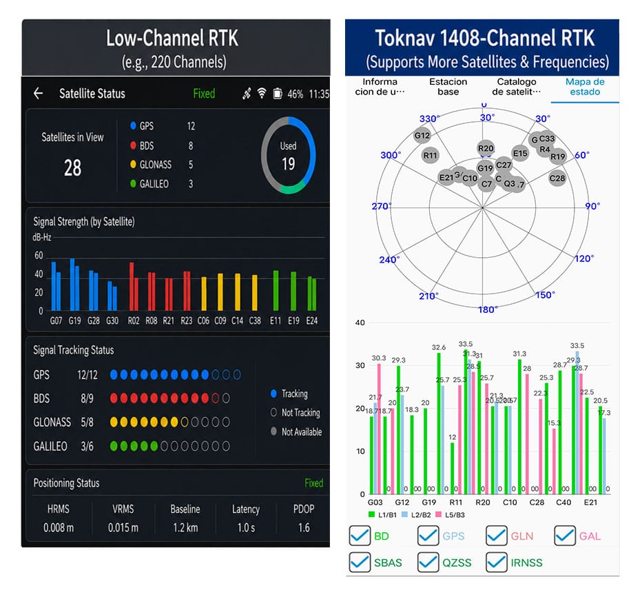
Home Benefits of 1408 Channels: Superior RTK Performance for Modern Multi-Constellation GNSS 2026-06-11 Benefits of Toknav 1408 Channels Benefits of 1408 Channels: Why Toknav’s Full RTK Lineup Leads in Multi-Constellation GNSS Positioning 1. Basic Knowledge of RTK Channel Count in GNSS Receivers 1.1 What Is an RTK Channel and Its Core Function Each RTK channel acts as an independent signal link to capture, demodulate and process satellite signals. A standard GNSS satellite transmits multiple frequency signals, and every signal requires a dedicated channel. The total RTK channel count directly decides how many satellite signals a receiver can track simultaneously in real time. RTK channel count comparison for 1400 channels GNSS and SOC RTK chip powered receivers 1.2 Drawbacks of Low-Channel Traditional RTK Devices Most old-generation RTK units only carry 100 to 600 channels. They can merely track a small number of satellites from limited constellations. In blocked areas like urban canyons or dense forests, they fail to collect enough signals, leading to slow search and frequent RTK fix loss on job sites. 1.3 How Channel Count Links to Multi-Constellation GNSS Operation Modern GNSS systems combine GPS, BeiDou, Galileo, GLONASS, QZSS and SBAS. Hundreds of satellites and diverse frequency signals operate in the air. Low-channel RTK cannot fully utilize these resources, becoming a bottleneck for high-efficiency modern positioning tasks. 2. Why 1400+ Channels Are Indispensable for Professional GNSS RTKH3: 2.1 Multi-Constellation Expansion Drives Demand for High Channel Capacity Global GNSS constellations keep expanding with new satellites and upgraded frequency signals launched each year. This clearly explains why 1400 channels GNSS has evolved from an advanced feature to a standard requirement for professional survey and positioning equipment worldwide. 2.2 1408 Channels: Full Coverage of All Mainstream GNSS Signals Toknav’s 1408 channels support full tracking of all constellations and multi-frequency signals. Unlike mid-range 800–1200 channel RTK, it never abandons weak yet valuable signals. It maximizes satellite resources to lay a foundation for stable positioning in complex scenarios. 2.3 Strong Anti-Interference and Adaptability of 1408-Channel Design Signal shielding and multipath interference are common in construction and mountainous regions. 1408 channels capture scattered satellite signals that low-channel devices miss. It optimizes satellite geometric distribution to reduce positioning errors and enhance overall reliability. 2.4 Long-Term Value: Future-Proof for Upcoming GNSS Upgradese Can Do It Satellite signal systems will continue to iterate in the next decade. A 1408-channel RTK can adapt to new satellite signals without hardware replacement. It helps users avoid repeated equipment updates and cuts long-term operating costs for engineering teams. Get 1408-Channel RTK Technical Datasheet & Quotation 3. Toknav’s SOC RTK Chip: The Core Power Supporting 1408 Full Channels 3.1 Definition and Advantages of Toknav’s Integrated SOC RTK Chip Toknav equips all RTK products with a self-developed high-performance SOC RTK chip. This system-on-chip integrates RF front-end, baseband, navigation engine and processor into one unit, replacing bulky discrete chip groups used in traditional RTK receivers. 3.2 How SOC RTK Chip Solves Multi-Channel Data Congestion Discrete chips often suffer data delay and congestion when running hundreds of channels. Toknav’s SOC RTK chip adopts optimized circuit architecture and algorithms. It distributes signal processing tasks evenly across 1408 channels to maintain ultra-low latency operation. 3.3 Power Efficiency of SOC RTK Chip for Portable RTK Devices Handheld RTK like T5 and T5Lite requires long outdoor working hours. The low-power design of Toknav’s SOC RTK chip minimizes energy consumption during full-channel operation. Users get extended battery life without sacrificing 1408-channel performance. 3.4 High Stability of SOC RTK Chip for Long-Hour Base Station Use For tBase and NET660 series base station RTK that run 24/7, the SOC RTK chip delivers stable continuous operation. It supports long-term multi-channel signal output to rovers, ensuring consistent signal transmission for large-scale CORS networks. SOC RTK chip core component supporting 1400 channels GNSS and high RTK channel count 4. Faster Satellite Acquisition and RTK Fix: The Most Obvious Benefit of 1408 Channels 4.1 Accelerated Full Satellite Search Speed Satellite acquisition is the first step of all RTK workflows. Toknav’s 1408 channels scan signals from all constellations in parallel, instead of group-by-group scanning. Field tests prove it completes full satellite search far faster than conventional low-channel RTK receivers. 4.2 Shortened RTK Fixed Solution Convergence Time RTK fix refers to centimeter-level high-precision positioning. 1408 channels collect massive valid satellite data for positioning algorithms. Rich signal samples speed up data calculation, greatly shortening the time to obtain a stable RTK fixed solution. 4.3 Rapid Reacquisition After Temporary Signal Blockage Field environments often have sudden signal occlusion from buildings or trees. Low-channel RTK needs dozens of seconds to re-search satellites. Toknav’s 1408 channels keep connecting with backup satellites and regain RTK fix within seconds to avoid work interruption. 4.4 Performance Comparison: 1408 Channels vs Ordinary Low-Channel RTK Standard 200–500 channel RTK spends 60 to 90 seconds to finish search and fix. Toknav 1408-channel RTK only needs 20 to 35 seconds for the same process. This efficiency gap directly raises daily output for surveying and mapping teams. Field test of 1400 channels GNSS RTK with great RTK channel count and SOC RTK chip 5. Toknav Entire RTK Product Line: Every Model Equipped with 1408 GNSS Channels 5.1 Economical & Handheld Portable RTK Series All lightweight handheld RTK models adopt 1408 channels, including budget-friendly T5Lite, portable T5 and engineering-standard T10Pro. They deliver fast search and fix for land planning, rural survey and basic construction measurement tasks. 5.2 High-End Laser, AR and Photogrammetry RTK Series Mid-to-high-end models T30, T40, T50 and their Pro versions integrate laser ranging, dual cameras and AR stakeout functions. Even with extra modules, they retain complete 1408 channels, keeping core positioning speed unchanged. 5.3 Professional Base Station and CORS Dedicated RTK The professional tBase base station RTK and NET660 series for CORS system construction fully support 1408 channels. For fixed base stations, abundant channels ensure stable signal coverage for multiple rovers in large engineering projects. 5.4 Special RTK for Drones, Unmanned Vehicles and Navigation NET660i-H (positioning & orientation) and NET660i-1U (unmanned vehicles) also carry 1408 channels. In drone

Benefits of 1408 Channels: Superior RTK Performance for Modern Multi-Constellation GNSS Read More »

RTK base station range comparison

RTK Base Station Range: Radio vs. Network Link – Which Covers Your Needs?

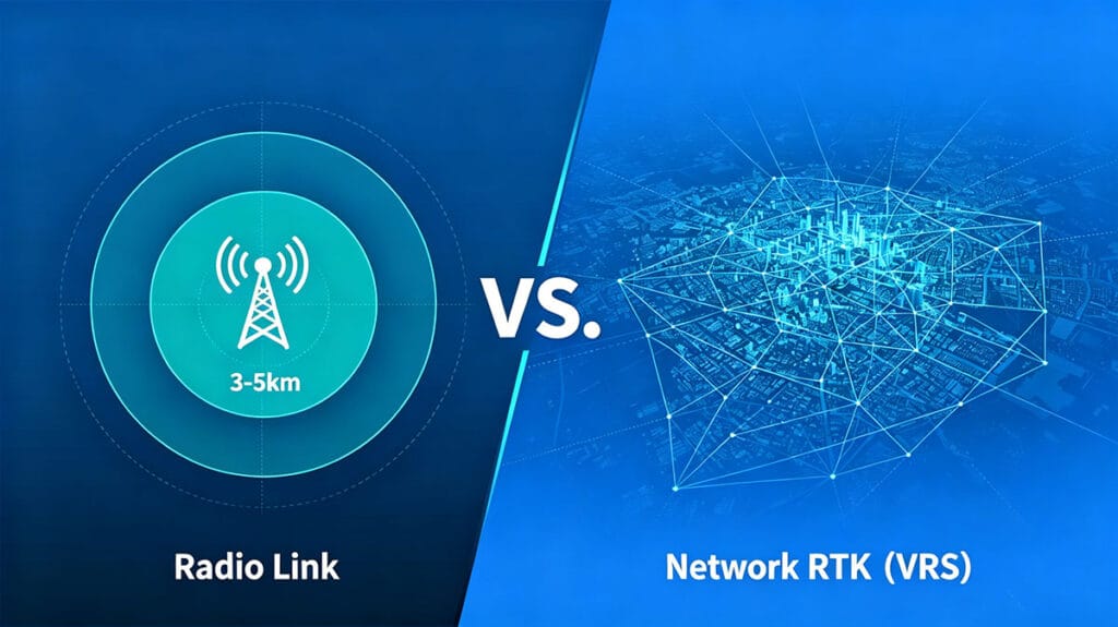
Home RTK Base Station Range: Radio vs. Network Link – Which Covers Your Needs? 2026-06-06 The Reach of Radio: Long Range RTK Capabilities For surveyors and mapping professionals, the base station’s operational range is a critical factor. Traditional RTK setups often rely on a physical radio link between the base and the rover. This method provides a direct, localized, and reliable connection independent of cellular networks. A common benchmark for a robust internal radio is a 3-5km line-of-sight range, a specification that defines true long-range RTK for many field applications. This capability is essential in remote construction sites, large-scale agricultural fields, or undeveloped land where internet connectivity is absent. The appeal lies in its self-contained nature—once the base is set up, the system creates its own positioning bubble, granting teams the freedom to operate within that radius without external dependencies. It’s the classic, proven workhorse for high-precision positioning. RTK base station range comparison: long range RTK radio vs. network coverage Discuss Your Project Needs Pushing the Limits: Understanding RTK Radio Distance The advertised RTK radio distance, such as 3-5km, represents an ideal, line-of-sight scenario. In practice, this range is influenced by terrain, obstacles, and antenna height. Dense urban environments with tall buildings or heavily forested areas can significantly reduce the effective operating radius. The internal radio power of the base station is the key driver behind this distance.Higher-power radios can penetrate mild obstructions better and maintain a stable data link at the edge of the nominal range. For a brand like TOKNAV, whose T50Pro and T40Pro RTK receivers are built for demanding photogrammetry and laser work, a strong, reliable radio link ensures that data integrity is maintained even as rovers move away from the base, preventing costly rework. The Power Within: Internal Radio Power and Its Role Internal radio power is the unsung hero of standalone RTK systems. It determines the signal strength and resilience of the data transmitted from the base to the rover. A unit with robust internal radio power, like those in TOKNAV’s RTK series, ensures a clearer signal at longer distances and in less-than-ideal conditions. This translates directly to field efficiency; surveyors can cover more ground without constantly moving the base station.However, it’s a localized solution. The radio’s coverage is a circle on the map with the base at its center. For projects larger than this circle—such as linear infrastructure projects spanning tens of kilometers or regional surveys—relying solely on radio becomes impractical, requiring multiple base setups or a different approach altogether. The Network Advantage: Unlimited Range with VRS/CORS This is where network solutions like Virtual Reference Station (VRS) or Continuously Operating Reference Stations (CORS) transform RTK operations. Instead of a single, user-deployed base station, the rover connects to a network of permanent, professionally maintained reference stations via cellular internet (4G/5G). Services like TOKNAV’s VRS Solution effectively create a virtual base station at the rover’s location, providing correction data over the internet. The coverage is no longer defined by a 5km radio bubble but by the cellular network’s footprint, which can be regional, national, or even continental. This eliminates the need to set up your own base, removes the range limitation, and is ideal for large-area or urban surveys. Request a Quote for Network Solutions Coverage Face-Off: 5km Radio vs. Continental Network Let’s directly compare the coverage models. A high-power RTK radio system offers a dedicated, secure link up to approximately 5km. Its performance is consistent and unaffected by cellular dead zones, making it a champion in remote locations. The limitation is strictly geographical. In contrast, a network RTK connection provides theoretically unlimited range wherever there is cellular data coverage. It offers incredible convenience for mobile teams and large-scale projects. The trade-off is the dependency on cellular service and potential subscription fees for the correction network. The choice isn’t about which technology is superior, but which is optimal for the specific project environment, scale, and logistical constraints. Choosing Your Tool: When to Use Radio or Network RTK Selecting the right data link is a strategic decision. Use a Long Range RTK radio link when: Toknav RTK receiver utilizing long range RTK radio in the field working in remote mines, quarries, offshore, or rural farmland with no cellular signal; on secure sites where external data connections are prohibited; or for short-duration, localized projects where setting up a single base is simpler and more cost-effective than managing network subscriptions. Opt for a Network RTK (VRS) link when:​ conducting surveys over a large city or a long, linear corridor like a highway or pipeline; working in areas with excellent cellular coverage; managing a fleet of rovers across a wide area; or when operational efficiency gains from not deploying a physical base outweigh the network cost. Toknav’s Toolkit: Solutions for Every Range Requirement TOKNAV’s product portfolio is strategically designed to support both operational paradigms. For traditional, radio-centric long-range RTK, their series of high-performance receivers like the T30 Pro​ (with Integrated Photogrammetry) and the T20Pro​ (Multifunctional Intelligent RTK) are engineered with powerful internal radios. For users looking to establish their own CORS network to blend control and coverage, the NET660i Base Station Receiver​ serves as a robust foundation. For the ultimate in extended range and convenience, leveraging their VRS Solution​ with a network-capable rover provides seamless, wide-area precision without range anxiety, perfect for GIS professionals using devices like the P8 Global. Flowchart: How to choose between RTK radio and network RTK for your base station range needs Get a Range Assessment for Your Equipment The Verdict on RTK Base Station Range There is no universal winner in the debate between radio and network RTK range. The 3-5km radio link provides dependable, self-contained control for defined sites, powered by the internal radio power​ of the base unit. The network link, powered by VRS technology, offers near-unlimited RTK radio distance​ by leveraging cellular infrastructure, redefining what long range RTK​ truly means.The most advanced operations often employ a hybrid approach, using radio for critical, signal-devoid sites and switching to network mode in covered

RTK Base Station Range: Radio vs. Network Link – Which Covers Your Needs? Read More »

Become TOKNAV global distributors!

With a proven track record in surveying industry, we’re now looking for passionate distributors to join our global success story.