jeffreyrtk@gmail.com

Hallo, ich bin Jeffrey, der Gründer von toknavgnss.com. Ich leite seit 8 Jahren eine Fabrik in China, die GNSS RTK herstellt, und der Zweck dieses Artikels ist es, mit Ihnen das Wissen über GNSS aus der Sicht eines chinesischen Lieferanten zu teilen.

TOKNAV 1a3f47bf68f65704832db732d45c8272
TOKNAV TCA920 GNSS antenna for CORS reference station projects

GNSS Antenna Selection Guide for RTK, CORS and Monitoring

Antenna Selection GNSS Antenna Selection Guide for RTK, CORS and Monitoring The GNSS antenna is a critical part of RTK rover, base station, CORS, VRS and deformation monitoring projects. Use this guide to compare signal support, installation environment, multipath risk, mounting, cable length and receiver compatibility. Request antenna support View GNSS antennas Author: TOKNAV GNSS Solution Team Reviewed by: TOKNAV Product and Field Application Team Last Updated: July 2026 Download the GNSS Antenna PDF Checklist Get a printable antenna selection checklist for receiver compatibility, signal support, mounting, multipath risk, cable planning and fixed-station installation. Name Company Email Country Project note Website Send me the PDF checklist By submitting, you agree that TOKNAV can contact you about this resource and related project support. A receiver can only work with the signal quality it receives. In open field RTK, the antenna choice affects setup stability and repeatability. In CORS, VRS and deformation monitoring projects, antenna installation can affect long-term data quality, multipath behavior and maintenance risk. This guide helps buyers compare antennas for projects using TOKNAV GNSS receivers, CORS receivers such as NET660i, base station workflows and reference station antennas such as TCA920. 1. Match the Antenna to the Application Application Antenna priority Related page RTK rover surveying Portable installation, stable signal reception, compatibility with receiver workflow. GNSS Receiver Local RTK base station Clear sky view, stable mount, cable plan and signal reliability for the project area. VRS vs RTK Base Station CORS or VRS station Permanent mounting, multipath suppression, weather exposure, grounding and maintenance access. CORS Station Checklist Deformation monitoring Stable installation, repeatable signal environment, protected cable routing and reliable data continuity. Monitoring Guide 2. Check Signal, Mounting and Multipath Conditions Signal requirements Confirm receiver model and supported constellations/frequencies. Confirm whether the project needs RTK, CORS, VRS, monitoring or mixed use. Check whether future receiver upgrades should be supported. Installation environment Open sky visibility and possible obstructions. Nearby metal, walls, water, machinery or reflective surfaces. Wind, rain, dust, cable exposure and maintenance access. Cable and accessory plan Cable length, connector type and protection method. Mounting pole, monument, enclosure and grounding. Lightning protection and service replacement plan. 3. When to Consider a Choke Ring Antenna Choke ring antennas are commonly considered for fixed reference station, CORS, VRS and high-precision monitoring projects because they are designed to help reduce multipath effects in demanding installation environments. Consider a choke ring antenna such as TCA920 when the project involves a permanent or semi-permanent station, high-value correction data, long-term observation, or an environment where reflected signals may affect data quality. TCA920 is a relevant option for fixed reference station, CORS, VRS and monitoring projects where multipath control and stable signal reception are important. 4. Information to Send for Antenna Recommendation Receiver model and project type. Country, installation environment and site photos. Mounting method, cable length and enclosure requirements. Required signals, data workflow and accuracy target. Whether the antenna is for rover, base station, CORS, VRS or monitoring use. Internal Planning Links Download antenna PDFs View GNSS case studies Plan VRS infrastructure Ask TOKNAV for antenna selection FAQ: GNSS Antenna Selection Is the antenna as important as the GNSS receiver? Yes. The antenna affects the signal quality received by the system, especially in reference station, CORS, VRS and monitoring projects where long-term stability matters. When should I use TCA920? TCA920 is a relevant option to evaluate for reference station, CORS, VRS and monitoring installations where multipath suppression and stable receiving performance are important. What information is needed to recommend an antenna? Send the receiver model, project type, installation photos, mounting method, cable length, required signals and accuracy target. Can one antenna fit all projects? No. Rover, base station, CORS and monitoring projects have different installation and signal requirements. The antenna should match the workflow and environment. Request GNSS Antenna Selection Support Send your receiver model, project type, site photos, cable plan and required signals. TOKNAV can help compare antenna and accessory options for your GNSS workflow. Contact TOKNAV View TCA920

GNSS Antenna Selection Guide for RTK, CORS and Monitoring Weiterlesen »

GNSS Deformation Monitoring Guide for Dams, Slopes, Mines and Bridges

Monitoring Guide GNSS Deformation Monitoring Guide for Dams, Slopes, Mines and Bridges This guide helps project owners, monitoring integrators and survey teams define a GNSS deformation monitoring project before choosing receivers, antennas, communication, power and reporting workflows. Request monitoring plan View monitoring solution Author: TOKNAV GNSS Solution Team Reviewed by: TOKNAV Product and Field Application Team Last Updated: July 2026 Download the GNSS Monitoring PDF Checklist Get a printable deformation monitoring checklist for point layout, reference points, accuracy targets, power, communication, reporting and quotation preparation. Name Company Email Country Project note Website Send me the PDF checklist By submitting, you agree that TOKNAV can contact you about this resource and related project support. GNSS deformation monitoring is used when a project needs continuous or repeated observation of movement trends. It can support dams, slopes, mines, bridges, buildings, tailings reservoirs and construction sites where small displacement changes matter for engineering judgment and risk management. A successful monitoring project starts before hardware selection. Teams should first define the object, monitoring points, reference point, required accuracy, data interval, power supply, communication and reporting workflow. Then they can compare NET660i, GNSS antennas, U6 monitoring devices and related solution components. Monitoring proposals should connect field conditions, point layout, receiver and antenna planning, data workflow and reporting needs. 1. Define the Monitoring Objective Object type Dam, reservoir or water infrastructure. Slope, landslide, mine or tailings site. Bridge, building or construction structure. Long-term reference or infrastructure monitoring network. Movement question Is the object stable or moving? Which direction and rate matter? What threshold needs attention? Who receives reports or alerts? Project constraints Power supply and weather exposure. Communication coverage and data access. Installation safety and maintenance access. Budget, phase plan and expansion needs. 2. Plan Monitoring Points and Reference Points Monitoring points should represent the critical movement zones. Reference points should be stable enough to support comparison and trend evaluation. Before requesting a proposal, prepare a simple point map with photos, approximate coordinates and installation notes. Mark each monitoring point and explain why it matters. Identify at least one suitable reference point or reference station concept. Record sky visibility and possible obstructions near each point. Confirm mounting surface, cable route, enclosure and maintenance access. Separate required accuracy from reporting frequency; both affect system design. 3. Choose Receiver, Antenna and Communication Components Project need Design question Related TOKNAV path Stable GNSS data Does the point need permanent high-precision GNSS observation? NET660i or appropriate GNSS receiver planning Signal quality Is the antenna installed near structures, slopes, water or reflective surfaces? GNSS Antenna Selection Guide Reference workflow Will the project use local base, CORS, VRS or another correction source? CORS Station Setup Checklist Data and alerts What data interval, reporting output and warning workflow are required? GNSS Deformation Monitoring Solution 4. Monitoring Project Checklist Send these details to TOKNAV Country, project type and monitored object. Number of monitoring points and reference points. Required accuracy, data interval and reporting frequency. Site photos, approximate layout and installation constraints. Power source, communication method and maintenance access. Do not leave these undefined Whether exact alarm thresholds are required. Who owns installation, maintenance and data review. How long data must be stored and exported. Whether the system must expand to more points later. Which claims can be publicly used in a case study. Related Case and Resource Links GNSS Monitoring Case Studies Download monitoring resources Compare GNSS receivers VRS and CORS infrastructure FAQ: GNSS Deformation Monitoring What sites can use GNSS deformation monitoring? GNSS deformation monitoring can support dams, slopes, mines, bridges, buildings, tailings reservoirs and other sites where long-term movement trends must be observed. How many monitoring points are needed? The number depends on the monitored object, risk zones, required resolution and reporting plan. A simple point map helps TOKNAV recommend a practical configuration. Can monitoring use CORS or VRS infrastructure? Some monitoring projects can connect with reference station, CORS or VRS workflows. The best design depends on site layout, accuracy target and communication conditions. What information is needed before quotation? Prepare country, object type, point quantity, accuracy target, data interval, power supply, communication method, site photos and reporting requirements. Request a GNSS Monitoring Solution Plan Share your monitoring object, point quantity, country, site photos, data interval and accuracy target. TOKNAV can help prepare a receiver, antenna, communication and reporting configuration. Contact TOKNAV View case studies

GNSS Deformation Monitoring Guide for Dams, Slopes, Mines and Bridges Weiterlesen »

TOKNAV CORS and VRS reference station network workflow

CORS Station Setup Checklist for GNSS Reference Networks

CORS / Reference Station CORS Station Setup Checklist for GNSS Reference Networks Use this checklist when planning a GNSS CORS station, VRS reference network or permanent RTK correction site. It covers the site, receiver, antenna, power, communication, testing and maintenance details that should be confirmed before quotation and installation. Request CORS configuration View VRS Solution Author: TOKNAV GNSS Solution Team Reviewed by: TOKNAV Product and Field Application Team Last Updated: July 2026 Download the CORS/VRS PDF Checklist Get a printable CORS and VRS station planning checklist for site selection, receiver and antenna choice, power, communication, testing and maintenance handover. Name Company Email Country Project note Website Send me the PDF checklist By submitting, you agree that TOKNAV can contact you about this resource and related project support. A good CORS station is not only a receiver on a roof. For reliable network RTK, VRS, monitoring or reference-station operation, the project team must control the station environment, antenna installation, data communication, power continuity and maintenance workflow. This checklist is written for survey organizations, distributors, system integrators and infrastructure owners comparing products such as NET660i, NET660, tBase and TCA920. NET660i is a compact starting point for CORS, reference station and augmentation-system planning. NET660 supports reference station infrastructure where stable GNSS data output and network workflow matter. 1. Confirm the CORS Station Purpose Project role Single permanent reference station for local RTK users. Multi-station CORS network for city or regional correction coverage. VRS network RTK service for multiple rover users. Reference data source for monitoring, agriculture or machine control. Buyer inputs to collect Country or region, coverage area and expected rover users. Station quantity and whether the network will expand later. Expected correction method, data format and service workflow. Target applications: surveying, construction, monitoring, agriculture or mixed use. 2. Select a Stable Station Site Site selection is the first technical filter. A receiver with strong tracking still needs an installation point with clear sky visibility and a stable monument or mounting structure. Choose a location with open sky view and limited obstruction above the antenna. Avoid reflective surfaces, metal structures, walls, large machinery and high-voltage interference where possible. Confirm that the mounting point is stable and not affected by vibration or building movement. Check access for maintenance, cable routing, grounding and weather protection. Document the site with photos, coordinates, elevation, nearby obstacles and planned cable length. 3. Choose Receiver and Antenna Configuration Component Selection question TOKNAV starting point CORS receiver Does the project need permanent reference station operation, network communication and stable GNSS data output? NET660i or NET660 Base station receiver Is this a local base-rover workflow rather than a permanent CORS network? tBase GNSS antenna Does the site need multipath suppression and stable reference station signal reception? TCA920 or another suitable TOKNAV GNSS antenna Accessories What cable, mounting, lightning protection, enclosure and power accessories are required? Resource Center and project recommendation 4. Power, Communication and Data Workflow Checklist Power Main AC or DC power source. Backup power or UPS requirement. Grounding and lightning protection plan. Power stability during storms, outages or remote operation. Communication Ethernet, cellular, WiFi or other data link availability. Static IP, server access or Ntrip workflow requirements. SIM card, router, antenna and signal strength if cellular is used. Remote management and troubleshooting access. Data Required data format and correction service workflow. Sampling rate and storage requirements. Monitoring dashboard or control center needs. Rover user access and account management plan. 5. Installation Acceptance Checklist Receiver firmware, settings, station name and coordinates are documented. Antenna mounting is stable, level, protected and photographed. Cables are weather protected, labeled and routed safely. Power supply and backup plan are tested. Communication uptime is tested under normal operating conditions. Correction data output is checked with a rover or downstream workflow. Station logs, photos and maintenance notes are stored for handover. Internal Planning Links VRS vs RTK Base Station GNSS Antenna Selection Guide Compare GNSS Receivers View Case Studies FAQ: CORS Station Setup Which receiver should I start with for a CORS station? NET660i and NET660 are relevant starting points for CORS and reference station projects. The final selection should confirm station role, communication, data output and environment. Does a CORS station need a choke ring antenna? Many reference station projects benefit from an antenna designed for stable signal reception and multipath suppression. TCA920 is one TOKNAV option to evaluate for this role. What details should I send before asking for a quote? Send country, coverage area, station count, installation photos, power condition, communication plan, receiver preference, antenna environment and expected rover users. How is this different from a local RTK base station? A local RTK base station usually supports one project or jobsite. A CORS or VRS network is planned for permanent reference data, broader coverage and multiple users. Request CORS Station Configuration Support Send your country, station quantity, coverage target, antenna environment, power condition and communication plan. TOKNAV can help compare receiver, antenna and accessory options. Contact TOKNAV Download resources

CORS Station Setup Checklist for GNSS Reference Networks Weiterlesen »

TOKNAV CORS and VRS reference station network workflow

VRS vs RTK Base Station: Which Correction Method Fits Your Project?

GNSS Correction Guide VRS vs RTK Base Station: Which Correction Method Fits Your Project? Compare VRS network RTK and local RTK base station workflows for surveying, CORS, monitoring and construction projects, with practical product paths for NET660i, NET660, tBase and GNSS antennas. Discuss CORS/VRS Project Download GNSS resources Author: TOKNAV GNSS Solution Team. Reviewed by TOKNAV Product and Field Application Team. Last updated: July 2026. When a surveying team, construction contractor, CORS operator or system integrator plans a high-precision GNSS project, one of the first questions is simple but important: should the project use a local RTK base station or a VRS network RTK workflow? Both methods can support centimeter-level positioning when designed and operated correctly, but they are not the same. A local RTK base station is often practical for a single jobsite or short-term project. A VRS network is better suited to wider-area correction coverage, shared rover users and long-term infrastructure. Local RTK base workflows usually start with one base receiver and one or more rover receivers. VRS and CORS workflows use multiple reference stations and correction distribution for wider coverage. What Is a Local RTK Base Station? A local RTK base station is a GNSS receiver installed at a known point. It sends correction data to one or more rover receivers by radio, network connection or another supported data link. The rover uses the correction data to improve positioning accuracy for field work. Common Applications Construction layout and stakeout. Topographic survey on a defined project site. Field work where public or private network RTK coverage is unavailable. Short-term survey projects that need local control. Dealer demonstration kits and training workflows. TOKNAV Product Path TOKNAV tBase can support base-rover workflows, while RTK rovers such as T50Pro, T40Pro, T20Pro and T10Pro can be selected according to field needs. What Is a VRS Network RTK Workflow? A VRS network RTK workflow uses multiple reference stations and network correction processing to support rover users across a wider planned area. Instead of relying on one local base station for one project area, the network collects data from several reference stations and provides corrections through a correction service workflow. Best-Fit Projects Regional or city-level correction coverage. Multiple rover users working in different locations. Stable infrastructure for surveying, monitoring, agriculture or machine positioning. A correction service managed by an organization, distributor, agency or system integrator. Long-term operation rather than one short field job. TOKNAV Product Path TOKNAV VRS Solution connects CORS/reference station receivers, GNSS antennas, data communication and project planning support for this kind of infrastructure. Quick Comparison: VRS Network RTK vs Local RTK Base Decision factor Local RTK base station VRS network RTK Best fit One jobsite, one team or short-term project area. Wider-area correction coverage with multiple users or long-term operation. Infrastructure One base receiver, rover receivers and data link. Multiple reference stations, antennas, communication and correction service workflow. Setup complexity Lower. Good for project teams that need fast field deployment. Higher. Requires planning for station locations, communications, server/workflow and maintenance. Scalability Limited to local project needs and data-link condition. Better for many rover users and larger coverage areas. Typical TOKNAV products tBase with RTK rover receivers such as T20Pro, T10Pro, T40Pro or T50Pro. NET660, NET660i, TCA-series antennas such as TCA920 and VRS/CORS project support. When Should You Choose Each Method? Choose a Local RTK Base Station When The project is limited to one site. The work period is temporary. Network RTK coverage is weak or unavailable. The team needs direct control over the correction source. The buyer wants a package that is easier to train and deploy. Choose VRS or CORS Infrastructure When Many users need correction access across a planned region. The project needs long-term reference station operation. Correction data must be distributed by network workflows such as Ntrip. The solution may support surveying, monitoring, agriculture or machine control together. The buyer is building a correction service or infrastructure system. Questions to Answer Before Requesting a Quote For a Local RTK Base Station Package What is the application: surveying, construction, road, GIS or training? How large is the project area? Will correction data use radio, network or another link? How many rover receivers are needed? What battery, controller, software and accessory needs should be included? For a VRS or CORS Project Which country or region needs coverage? How many reference stations are planned? What are the station installation environments? What antenna type and mounting conditions are expected? How will data communication, power supply and server workflow be handled? Recommended TOKNAV Product Paths Project need Recommended starting point Next action RTK surveying with local correction tBase plus RTK rover receivers. Request a base-rover package recommendation. CORS or VRS infrastructure NET660i, NET660 and suitable antennas. Share station count and coverage plan. Reference station antenna selection TCA920 or another TOKNAV GNSS antenna. Send receiver model, mounting environment and required signals. Monitoring and long-term infrastructure GNSS Deformation Monitoring with receiver and antenna planning. Send monitoring point quantity, site condition and data interval needs. Next Planning Resources After comparing VRS network RTK and a local RTK base station, use these resources to move from correction method selection to station design, antenna selection, proof review and inquiry preparation. CORS Station Setup Checklist GNSS Antenna Selection Guide GNSS Deformation Monitoring Guide TOKNAV Case Studies Resource Center Contact TOKNAV FAQ: VRS vs RTK Base Station Is VRS always better than a local RTK base station? No. VRS is better for wider-area network correction coverage and many users, while a local RTK base station can be simpler and more practical for one project site or a temporary field job. Which TOKNAV receiver should be used for CORS or VRS projects? NET660 and NET660i are relevant starting points for CORS and reference station projects. The final choice should be confirmed by station design, data link, antenna environment and project requirements. Which TOKNAV receiver should be used as a local base station? tBase is a practical starting point for base-rover RTK workflows. Pair it with suitable TOKNAV rover receivers according

VRS vs RTK Base Station: Which Correction Method Fits Your Project? Weiterlesen »

TOKNAV GNSS field application case study

TOKNAV Case Studies

Case Studies TOKNAV GNSS Case Studies: CORS, Monitoring, USV and Robots Real-world and publicly usable TOKNAV application stories for CORS/VRS planning, deformation monitoring, sports field marking robots, hydrographic survey, agriculture and machine control. Each case summarizes the country or buyer context, equipment, workflow, buyer result and next step for similar projects. Request a similar solution View resource center Customer names are kept anonymous unless already approved for public use. Where a public customer name or exact site is not approved, the case is presented as an application case with buyer context, equipment path and verifiable planning outcome instead of invented names or unsupported claims. Priority Application Cases France: RTK Base-Rover Road Resurvey Country: France Industry: Road surveying and engineering resurvey Equipment: TOKNAV GNSS base-rover kit, RTK rover workflow, UHF plus 4G fallback communication Challenge: A rural road resurvey team faced a tight deadline, mixed open farmland and tree-lined sections, and unstable cellular coverage. Workflow: The team set a fixed base station on a certified control point with open sky view, then used UHF where cellular coverage was weak and 4G fallback across open sections. Result: The team achieved consistent centimeter-level accuracy, avoided rework and finished the 12 km road project two days ahead of schedule. Read the source application story Philippines: Tboat USV Hydrographic Survey and Monitoring Country: Philippines Industry: Hydrographic survey, bathymetry and water quality monitoring Equipment: Tboat10, Tboat20, RTK positioning, echo sounder and water-quality payload options Challenge: Local teams needed safer and more repeatable water survey workflows for coastal shallow water, rivers and remote island conditions. Workflow: Tboat USVs supported automatic route planning, real-time video/data feedback, RTK positioning and flexible payload integration for survey and monitoring tasks. Result: Philippine users reported stable field performance, accurate depth data, easier transport and lower manual risk compared with traditional boat-based workflows. Read the source application story RTK and GNSS field cases should connect product setup, communication method and measurable project result. Monitoring and infrastructure cases should document site condition, point layout, data workflow and reporting needs. CORS/VRS Infrastructure: Reference Station Planning Case Country: Project country to be confirmed by buyer Industry: CORS, VRS, reference station and network RTK infrastructure Equipment: NET660, NET660i, tBase, TCA920 and station accessories Challenge: Buyers often request a CORS/VRS quote before confirming station count, antenna environment, communication, power and expected rover users. Workflow: TOKNAV first collects country, coverage area, station quantity, receiver preference, antenna environment and data communication plan. Result: A clearer station plan helps the buyer compare receiver, antenna, server/workflow and maintenance requirements before procurement. Use the CORS station setup checklist Deformation Monitoring: Dam, Slope and Infrastructure Planning Case Country: Buyer-defined infrastructure site Industry: GNSS deformation monitoring for dams, slopes, mines, bridges and buildings Equipment: NET660i, TCA920, monitoring devices, power and communication components Challenge: Monitoring buyers need to define point quantity, reference points, accuracy target, data interval, power, communication and alert workflow before hardware selection. Workflow: TOKNAV uses a project intake checklist to connect site photos, point layout and reporting requirements with receiver, antenna and communication planning. Result: The buyer can move from a broad monitoring request to a clearer bill of materials and integration discussion. Use the monitoring planning guide Sports Field Marking Robot: Soccer and Multi-Sport Venue Case Country: Venue or contractor market to be confirmed by buyer Industry: Sports facility construction, campus maintenance and field line marking Equipment: TR10Pro sports field marking robot with GNSS/RTK positioning and digital field templates Challenge: Venues and contractors need repeatable soccer, football, lacrosse, baseball and custom training layouts with less manual measuring and rework. Workflow: Operators choose a field template, confirm site conditions, prepare paint and RTK correction, then run a repeatable robotic marking path. Result: Facilities can standardize line marking quality and make multi-field preparation more predictable. View the TR10Pro field marking robot Agriculture and Machine Control: Field Leveling and Guidance Case Country: Farm, contractor or dealer market to be confirmed by buyer Industry: Precision agriculture, land leveling, dozer guidance and excavator guidance Equipment: TAG66, TAG88, TMC10, TMC20 and compatible GNSS receiver workflows Challenge: Dealers and project teams need to match steering, land leveling or machine control hardware with vehicle type, worksite condition and accuracy target. Workflow: TOKNAV collects crop or operation type, machine model, field or construction environment, correction method and expected deployment quantity. Result: Buyers receive a clearer product path before quotation instead of comparing unrelated agriculture and construction positioning products. View GNSS land leveling Additional Public Proof Story China, Hangzhou: Heritage Building Digitalization and Crack Discovery Country: China Industry: Heritage conservation, building digitalization and 3D mapping Equipment: TOKNAV TSR20 handheld LiDAR scanner with SLAM / RTK-SLAM workflows Challenge: A Qing Dynasty residence in Hangzhou required detailed digital documentation to support restoration planning. Workflow: TSR20 point clouds were combined with historical archive information to reconstruct building evolution and inspect structural details. Result: The scan revealed hidden structural cracks and provided a data foundation for restoration planning. Read the source application story Need to Turn a Project Into a Case Study? Best fit: Projects with approved photos, site context, product list and measurable result. Useful evidence: Field photos, screenshots, point layout, route map, survey output, monitoring graph or acceptance notes. Publishing rule: TOKNAV can keep customer names anonymous unless public approval is available. Submit a project for case study support Case Study Comparison Case Country Industry Equipment Buyer result RTK road resurvey France Road surveying GNSS base-rover kit, RTK rover, UHF/4G workflow Centimeter-level accuracy and 12 km project completed two days ahead of schedule. Tboat hydrographic survey Philippines Hydrographic survey and water monitoring Tboat10, Tboat20, RTK positioning and payload integration Stable field performance, safer water survey workflow and easier daily deployment. Heritage building digitalization China Heritage conservation and 3D mapping TSR20 handheld LiDAR scanner Hidden cracks identified and restoration planning supported by point cloud data. CORS/VRS station planning Buyer-defined Reference station infrastructure NET660, NET660i, tBase, TCA920 Clearer receiver, antenna, communication and maintenance plan before quotation. Deformation monitoring planning Buyer-defined Dams, slopes, mines, bridges and buildings NET660i, TCA920, monitoring devices Monitoring points, accuracy, data interval

TOKNAV Case Studies Weiterlesen »

TOKNAV T50Pro GNSS receiver for RTK surveying resources

TOKNAV Resource Center

Resource Center TOKNAV GNSS Receiver Datasheets, Brochures and Buying Resources Download TOKNAV brochures, product datasheets, solution documents and buyer checklists for RTK surveying, CORS/VRS infrastructure, GNSS antennas, deformation monitoring, rugged GIS and positioning solution projects. Request model recommendation Compare GNSS receivers If you are comparing models or preparing a project quotation, send your application, country, required accuracy, correction method and target product family to TOKNAV for model selection support. Implementation Guides and Project Checklists Use these high-intent guides before requesting a quote. The CORS/VRS, deformation monitoring and GNSS antenna guides now include PDF checklist request forms so the sales team can follow up with the right project context. CORS Station Setup Checklist Plan a reference station from site selection through receiver, antenna, power, communication, installation and maintenance. Includes a gated downloadable PDF checklist. Open the CORS checklist and PDF request form GNSS Deformation Monitoring Guide Prepare monitoring points, reference points, receivers, antennas, data intervals, power and reporting workflows for infrastructure projects. Includes a gated downloadable PDF checklist. Open the monitoring guide and PDF request form GNSS Antenna Selection Guide Compare antenna choices for RTK rover, base station, CORS/VRS and long-term monitoring installations. Includes a gated downloadable PDF checklist. Open the antenna guide and PDF request form TOKNAV Case Studies Review country, industry, equipment, workflow and result examples before preparing a similar GNSS, RTK, USV or LiDAR project. View case studies GNSS Receiver Brochures and Datasheets Start here if you need RTK rover receivers, base station receivers, CORS receivers or a complete receiver package for surveying and construction workflows. GNSS Receiver Brochure T50Pro GNSS Receiver PDF T40Pro GNSS Receiver PDF T20Pro GNSS Receiver PDF T10Pro GNSS Receiver PDF NET660i CORS GNSS Receiver PDF NET660 GNSS Receiver PDF tBase GNSS Base Station Receiver PDF Solution Documents CORS, VRS and Monitoring These resources help project owners, distributors and system integrators prepare reference station, correction service and monitoring projects. Solution Brochure VRS Solution page CORS Station Setup Checklist GNSS Deformation Monitoring page GNSS Deformation Monitoring Guide Agriculture, Machine Control and USV Use these pages when the project involves land leveling, dozer guidance, unmanned surface vehicles or machine positioning workflows. GNSS Land Leveling Solution Machine Control Solution Unmanned Surface Vehicle Solution VRS and CORS solution resources for correction service planning. Field application resources for surveying, monitoring and infrastructure projects. GNSS Antennas, Accessories and Field Collection GNSS Antennas GNSS Antennas Brochure TCA920 Choke Ring GNSS Antenna PDF GNSS Antenna Selection Guide GNSS Antenna category Accessories Accessories category Accessories Brochure Rugged GIS Rugged and GIS Brochure P8/P8Pro Portable RTK Receiver PDF Rugged and GIS category Buyer Checklists RTK Receiver Selection Application: surveying, construction, GIS, agriculture, machine control or monitoring. Required accuracy and correction method: local base, radio, network RTK, VRS, PPP or other workflow. Field environment: urban, open field, mountain, mine, road, dam, bridge or campus. Preferred features: IMU tilt, visual measurement, radio, 4G, battery life, rugged body or lightweight design. CORS/VRS Project Country or region and planned coverage area. Station quantity, receiver model preference and antenna installation environment. Data communication plan, power supply condition and server or platform requirements. Expected rover users, accuracy target and project timeline. Monitoring Project Object to monitor: dam, slope, mine, bridge, building, tailings reservoir or construction site. Number of monitoring points and reference points. Accuracy target, data interval and reporting or alert requirements. Power supply, communication condition and installation environment. FAQ Which TOKNAV document should I download first? For general RTK receiver selection, start with the GNSS Receiver Brochure. For CORS, VRS or monitoring projects, also download the Solution Brochure, NET660i PDF and a relevant GNSS antenna document. Can TOKNAV recommend a product package after I send project details? Yes. Share your application, region, accuracy target, correction method, field environment and preferred product family so TOKNAV can recommend a receiver, antenna, software and accessory package. Are the PDFs enough for a distributor quotation? The PDFs are a good first step. Distributor or wholesale buyers should also include target market, sales channel, expected product demand, support needs and active project information. Do CORS and deformation monitoring projects need custom configuration? Yes. CORS, VRS and monitoring projects should be planned around station count, installation environment, communication, power, target accuracy and long-term maintenance requirements. Request a Recommendation Send your project type, country, required accuracy, correction method and target product family to TOKNAV. The team can help compare models, prepare documents and recommend a suitable package. Contact TOKNAV Distributor cooperation

TOKNAV Resource Center Weiterlesen »

Linienmarkierungsroboter TR10Pro

Der Linienmarkierungsroboter TR10Pro erhält ein neues weißes Gehäuse: Was Käufer wissen sollten

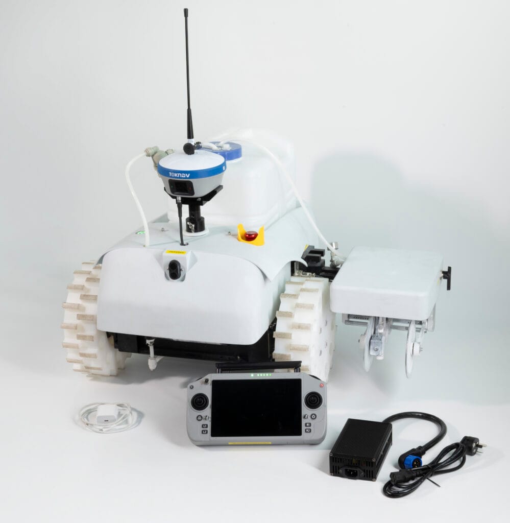
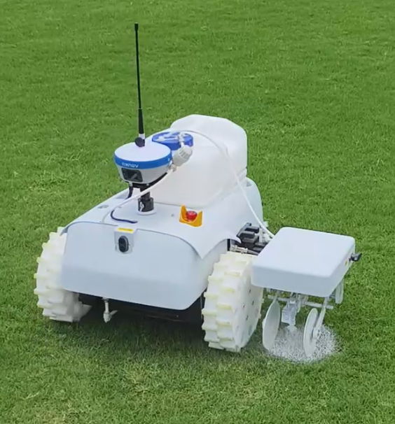
Startseite: Der Linienmarkierungsroboter TR10Pro erhält ein neues weißes Gehäuse – Was Käufer wissen sollten 19.06.2026 TOKNAV hat das äußere Erscheinungsbild des Linienmarkierungsroboters TR10Pro überarbeitet. Während die Vorgängerversion ein grünes Gehäuse hatte, verfügt die aktualisierte Version nun über ein klares weißes Gehäuse. Für ausländische Vertriebspartner, Sportplatzbauer, kommunale Straßenbauunternehmen und Projektkäufer ist dies mehr als nur eine einfache Farbänderung. Das neue weiße Gehäuse verleiht dem TR10Pro ein klareres Produktimage und eine technisch anmutende Optik. Zudem passt es besser zum blau-weißen GNSS-Markensystem von TOKNAV. Der TR10Pro positioniert sich weiterhin als automatisierte Linienmarkierungsroboterlösung für Vermessung, Markierung und die Automatisierung von Nebenarbeiten auf Sportplätzen. Er ist für Anwender konzipiert, die wiederholbare, GNSS-gesteuerte Linienmarkierungen auf Sportplätzen, Straßen, kommunalen Flächen und bei Projekten im Zusammenhang mit Start- und Landebahnen benötigen. Dieser Artikel erläutert, was sich geändert hat, was gleich geblieben ist und worauf B2B-Einkäufer achten sollten, bevor sie das aktuelle Datenblatt oder ein Angebot anfordern. Planen Sie die Anschaffung eines Linienmarkierungsroboters? Senden Sie uns Ihre Anwendungsbeschreibung, Ihr Land, die Art der Oberfläche und die gewünschte Stückzahl, damit TOKNAV Ihnen die passende TR10Pro-Konfiguration empfehlen kann. Senden Sie uns Ihre Markierungsanforderungen Warum TOKNAV den TR10Pro von Grün auf Weiß umgestellt hat Die Funktionen und Vorteile des Linienmarkierungsroboters TR10Pro im Überblick Bei Industrieausrüstung ist die Farbe nicht nur Dekoration; sie beeinflusst, wie ein Produkt auf Fotos, in Videos, Schulungsmaterialien, auf Messen und in Händlerkatalogen wahrgenommen wird. Das alte grüne Gehäuse des TR10Pro machte den Roboter leicht erkennbar, insbesondere vor dem Hintergrund von Außenaufnahmen. Da TOKNAV seine GNSS-Produkte, Empfänger und Komplettlösungen jedoch weiterhin im blau-weißen Markenstil präsentiert, verleiht das neue weiße Gehäuse dem Linienmarkierungsroboter eine einheitlichere visuelle Sprache. Das weiße Gehäuse trägt zudem dazu bei, dass das Produkt in Verkaufsmaterialien aufgeräumter wirkt. Eine robotergesteuerte Linienmarkierungsmaschine wird oft bereits bewertet, bevor der Käufer sie überhaupt persönlich in Augenschein nehmen kann. Importeure und Bauunternehmer vergleichen in der Regel Produktfotos, Demovideos, Datenblätter und Angebotsunterlagen. Ein weißes Äußeres kann dazu beitragen, dass Produktdetails, Räder, Düsenmechanismen, die Anordnung des Tanks und die Befestigungspositionen des Empfängers in Marketingbildern klarer dargestellt werden können. Dies ist für TOKNAV-Partner von Bedeutung, die möglicherweise Produktbilder für eine Website, ein Messebanner, einen WhatsApp-Katalog, einen LinkedIn-Beitrag oder Ausschreibungsunterlagen benötigen. Das aktualisierte weiße TR10Pro-Gehäuse lässt sich leichter mit blauen Markenelementen und neutralen Seitenhintergründen kombinieren und hilft Partnern so, professionellere Vertriebsinhalte ohne aufwendige Bildbearbeitung zu erstellen. Vergleich zwischen altem grünem und neuem weißem Gehäuse Punkt Altes grünes Gehäuse Neues weißes Gehäuse Visuelle Identität Starke Sichtbarkeit im Einsatz und ein praktischer Geräte-Look. Klarer, technischer und näher am blau-weißen TOKNAV-Branding. Präsentation auf der Website Eignet sich gut für Außenaufnahmen, wirkt jedoch im Vergleich zu den Seiten der GNSS-Empfänger möglicherweise weniger einheitlich. Passt besser zu Produktseiten, Landingpages, Katalogen und bezahlten Anzeigen. Vertrieb durch Händler Erkennbar, erfordert jedoch möglicherweise mehr Designanpassungen. Einfacher zu verwenden mit weiß-blauen Layouts, Vergleichsgrafiken und Anfrage-Seiten. Käuferwahrnehmung Funktional und praxisorientiert. Edler, moderner und professioneller für den B2B-Einkauf. Kernzweck Automatisierte, GNSS-gesteuerte Linienmarkierung. Automatisierte, GNSS-gesteuerte Linienmarkierung. Die endgültige Konfiguration sollte anhand des aktuellen Datenblatts überprüft werden. Vorgeschlagener Elementor-Bildblock: Vergleich zwischen altem und neuem Gehäuse – bisheriges grünes Gehäuse, aktualisiertes weißes Gehäuse. Was gleich bleibt: RTK-gesteuerter Markierungs-Workflow. Der wichtigste Punkt für Käufer ist einfach: Das neue weiße Äußere ist eine Aktualisierung des Produktdesigns, kein Grund, den zentralen Markierungs-Workflow außer Acht zu lassen. Der TR10Pro wird weiterhin als GNSS-gesteuerte robotergestützte Markierungslösung für Linienmarkierungsaufgaben beworben, die Wiederholbarkeit, reduzierten manuellen Aufwand und eine konsistente Ausführung der Markierung erfordern. Basierend auf den Produktunterlagen der TOKNAV TR10-Serie basiert die Lösung auf hochpräziser GNSS-Positionierung und automatisierter Markierungsausführung. Das System unterstützt die Linienmarkierung für Sportplätze, Autobahnen, kommunale Straßen und Anwendungen im Zusammenhang mit Flughafenlandebahnen. Es ist darauf ausgelegt, Anwendern dabei zu helfen, Markierungsdateien zu importieren oder vorzubereiten, geplanten Linien zu folgen und Markierungsaufgaben mit weniger manuellen Mess- und Schnurauslegungsarbeiten durchzuführen. Bei einer typischen Projektbesprechung sollten Käufer vor der Bestellung die aktuelle Konfiguration bestätigen. Wichtige Punkte sind dabei die Empfängerkonfiguration, die Korrekturmethode, unterstützte Dateiformate für den Import, die Art der Farbe, die Markierungsbreite, die Arbeitsumgebung, die Akkukonfiguration, der lokale Schulungsbedarf sowie Ersatzteile. Bei internationalen B2B-Bestellungen ist diese Überprüfung besonders wichtig, da in verschiedenen Ländern unterschiedliche Korrekturdienste, Geländebedingungen und Arbeitsgewohnheiten zum Tragen kommen können. Wichtige Produktmerkmale, nach denen Einkäufer üblicherweise fragen GNSS-gesteuerte Markierung: entwickelt für automatisiertes Auslegen und Markieren auf Basis hochpräziser Positionierung. Anwendungsbereich: geeignet für Sportplätze, Autobahnen, kommunale Straßen und die Vorbereitung von Markierungen im Zusammenhang mit Start- und Landebahnen. Vorlagen und Datei-Workflow: Unterstützt integrierte Markierungsvorlagen und gängige Projektdatei-Workflows gemäß den Materialien der TR10-Serie. Markierungsmechanismus: Konzipiert für die Linienmarkierung im Feld mit anpassbaren Markierungsanforderungen je nach Konfiguration. Eignung für die B2B-Beschaffung: Geeignet für Bauunternehmer, Händler, Dienstleister für Sportanlagen und Anbieter von öffentlichen Bauleistungen. Warum das weiße Gehäuse für B2B-Käufer wichtig ist Ein Linienmarkierungsroboter wird oft aufgrund von Vertrauen verkauft. Käufer möchten wissen, ob der Anbieter die Einsatzbedingungen vor Ort versteht, ob der Roboter den Bedienern leicht zu erklären ist und ob das Produktimage professionell genug für den lokalen Markt eines Händlers ist. Das neue weiße Gehäuse unterstützt diesen vertrauensbildenden Prozess auf verschiedene praktische Weisen. Erstens passt das Produkt optisch besser zu den GNSS-Empfängern von TOKNAV, bei denen Blau und Weiß bereits als zentrale visuelle Erkennungsmerkmale dienen. Dies ist wichtig, wenn der TR10Pro als Teil eines größeren GNSS-Lösungsportfolios und nicht als eigenständiger Roboter präsentiert wird. Zweitens bietet das weiße Gehäuse einen besseren Hintergrund, um Details wie den Tank, die Radaufbau, den Düsenbereich und die Empfängerhalterung hervorzuheben. Drittens verbessert es die Optik von Verkaufsseiten und Landingpages für bezahlte Werbung, wo klare Produktfotos den ersten Eindruck verbessern können, noch bevor ein Käufer die technischen Daten liest. Für Vertriebspartner kann dies Reibungsverluste verringern. Ein klareres Produktbild lässt sich leichter in verschiedene Märkte lokalisieren, einschließlich englischer, spanischer, französischer, arabischer, russischer und deutscher Verkaufsmaterialien. Es eignet sich zudem besser für Vergleichstabellen, Anfrage-Popups, Angebots-PDFs und Grafiken für Messestände. Anwendungsszenarien für die aktualisierte TR10Pro-Sportplatzmarkierung Sportplätze gehören zu den intuitivsten Anwendungsfällen für die robotergestützte Linienmarkierung. Sportplatzbetreiber benötigen wiederholbare Layouts, klare Begrenzungen und eine effiziente Neumarkierung. Die

Der Linienmarkierungsroboter TR10Pro erhält ein neues weißes Gehäuse: Was Käufer wissen sollten Weiterlesen »

Vergleich der RTK-Kanalanzahl bei Empfängern mit 1400-Kanal-GNSS und SOC-RTK-Chip

Vorteile von 1408 Kanälen: Überragende RTK-Leistung für moderne GNSS-Systeme mit mehreren Konstellationen

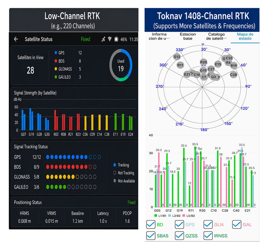
Startseite Vorteile der 1408 Kanäle: Überragende RTK-Leistung für moderne Multi-Konstellations-GNSS 11.06.2026 Vorteile der 1408 Kanäle von Toknav Vorteile der 1408 Kanäle: Warum die komplette RTK-Produktpalette von Toknav bei der Multi-Konstellations-GNSS-Positionsbestimmung führend ist 1. Grundlegendes zur Anzahl der RTK-Kanäle in GNSS-Empfängern 1.1 Was ist ein RTK-Kanal und welche Kernfunktion hat er? Jeder RTK-Kanal fungiert als unabhängige Signalverbindung zum Empfang, zur Demodulation und zur Verarbeitung von Satellitensignalen. Ein Standard-GNSS-Satellit sendet Signale auf mehreren Frequenzen aus, und jedes Signal benötigt einen eigenen Kanal. Die Gesamtzahl der RTK-Kanäle bestimmt direkt, wie viele Satellitensignale ein Empfänger gleichzeitig in Echtzeit verfolgen kann. Vergleich der RTK-Kanalanzahl bei Empfängern mit 1.400 Kanälen (GNSS) und Empfängern mit SOC-RTK-Chip 1.2 Nachteile herkömmlicher RTK-Geräte mit geringer Kanalanzahl Die meisten RTK-Geräte älterer Generation verfügen nur über 100 bis 600 Kanäle. Sie können lediglich eine geringe Anzahl von Satelliten aus begrenzten Konstellationen verfolgen. In abgeschirmten Bereichen wie städtischen Schluchten oder dichten Wäldern können sie nicht genügend Signale erfassen, was zu einer langsamen Suche und häufigen Verlusten der RTK-Position auf Baustellen führt. 1.3 Wie die Kanalanzahl mit dem Betrieb mehrerer GNSS-Konstellationen zusammenhängt Moderne GNSS-Systeme kombinieren GPS, BeiDou, Galileo, GLONASS, QZSS und SBAS. Hunderte von Satelliten und vielfältige Frequenzsignale sind am Himmel im Einsatz. RTK-Systeme mit geringer Kanalanzahl können diese Ressourcen nicht vollständig nutzen und werden so zu einem Engpass für hocheffiziente moderne Positionierungsaufgaben. 2. Warum mehr als 1.400 Kanäle für professionelles GNSS-RTK unverzichtbar sind: 2.1 Die Erweiterung um mehrere Konstellationen treibt die Nachfrage nach hoher Kanalkapazität an Globale GNSS-Konstellationen werden kontinuierlich erweitert, wobei jedes Jahr neue Satelliten und verbesserte Frequenzsignale in Betrieb genommen werden. Dies erklärt eindeutig, warum GNSS mit 1.400 Kanälen sich weltweit von einer fortschrittlichen Funktion zu einer Standardanforderung für professionelle Vermessungs- und Positionierungsgeräte entwickelt hat. 2.2 1.408 Kanäle: Vollständige Abdeckung aller gängigen GNSS-Signale Die 1.408 Kanäle von Toknav unterstützen die vollständige Verfolgung aller Konstellationen und Multifrequenzsignale. Im Gegensatz zu RTK-Geräten der Mittelklasse mit 800–1.200 Kanälen werden schwache, aber wertvolle Signale niemals außer Acht gelassen. Es nutzt die Satellitenressourcen optimal aus und schafft so die Grundlage für eine stabile Positionsbestimmung in komplexen Szenarien. 2.3 Hohe Störfestigkeit und Anpassungsfähigkeit des 1408-Kanal-Designs Signalabschirmung und Mehrwegstörungen sind im Bauwesen und in bergigen Regionen weit verbreitet. 1408 Kanäle erfassen gestreute Satellitensignale, die Geräte mit geringer Kanalanzahl übersehen. Es optimiert die geometrische Verteilung der Satelliten, um Positionsfehler zu reduzieren und die allgemeine Zuverlässigkeit zu verbessern. 2.4 Langfristiger Wert: Zukunftssicher für kommende GNSS-Upgrades – „Can Do It“ Satellitensignalsysteme werden sich im nächsten Jahrzehnt weiterentwickeln. Ein RTK-System mit 1408 Kanälen kann sich ohne Hardware-Austausch an neue Satellitensignale anpassen. Dies erspart Anwendern wiederholte Geräte-Updates und senkt die langfristigen Betriebskosten für Ingenieurteams. Technisches Datenblatt und Angebot für das 1408-Kanal-RTK-System anfordern 3. Der SOC-RTK-Chip von Toknav: Die Kernkomponente für die Unterstützung von 1408 Vollkanälen 3.1 Definition und Vorteile des integrierten SOC-RTK-Chips von Toknav Toknav stattet alle RTK-Produkte mit einem selbst entwickelten, leistungsstarken SOC-RTK-Chip aus. Dieser System-on-Chip integriert RF-Frontend, Basisband, Navigations-Engine und Prozessor in einer Einheit und ersetzt damit die sperrigen, diskreten Chipgruppen, die in herkömmlichen RTK-Empfängern verwendet werden. 3.2 Wie der SOC-RTK-Chip Datenstaus bei mehreren Kanälen löst Diskrete Chips leiden häufig unter Datenverzögerungen und -staus, wenn Hunderte von Kanälen betrieben werden. Der SOC-RTK-Chip von Toknav nutzt eine optimierte Schaltungsarchitektur und Algorithmen. Er verteilt die Signalverarbeitungsaufgaben gleichmäßig auf 1408 Kanäle, um einen Betrieb mit extrem geringer Latenz zu gewährleisten. 3.3 Energieeffizienz des SOC-RTK-Chips für tragbare RTK-Geräte Handheld-RTK-Geräte wie T5 und T5Lite erfordern lange Einsatzzeiten im Freien. Das stromsparende Design des SOC-RTK-Chips von Toknav minimiert den Energieverbrauch im Vollkanalbetrieb. Anwender profitieren von einer verlängerten Akkulaufzeit, ohne Abstriche bei der 1.408-Kanal-Leistung machen zu müssen. 3.4 Hohe Stabilität des SOC-RTK-Chips für den lang andauernden Einsatz als Basisstation Für RTK-Basisstationen der Serien tBase und NET660, die rund um die Uhr in Betrieb sind, gewährleistet der SOC-RTK-Chip einen stabilen Dauerbetrieb. Er unterstützt die langfristige Mehrkanal-Signalausgabe an Rover und gewährleistet so eine konsistente Signalübertragung für großflächige CORS-Netzwerke. SOC-RTK-Chip als Kernkomponente mit Unterstützung für 1.400 GNSS-Kanäle und hoher RTK-Kanalanzahl 4. Schnellere Satellitenerfassung und RTK-Fix: Der offensichtlichste Vorteil von 1.408 Kanälen 4.1 Beschleunigte Geschwindigkeit bei der vollständigen Satellitensuche Die Satellitenerfassung ist der erste Schritt aller RTK-Arbeitsabläufe. Die 1.408 Kanäle von Toknav scannen Signale aller Konstellationen parallel, anstatt gruppenweise zu scannen. Feldtests belegen, dass die vollständige Satellitensuche weitaus schneller abgeschlossen wird als bei herkömmlichen RTK-Empfängern mit geringer Kanalanzahl. 4.2 Verkürzte Konvergenzzeit der RTK-Fix-Lösung Ein RTK-Fix bezeichnet eine hochpräzise Positionierung im Zentimeterbereich. Die 1.408 Kanäle erfassen umfangreiche gültige Satellitendaten für die Positionsberechnung. Die große Anzahl an Signalproben beschleunigt die Datenverarbeitung und verkürzt die Zeit bis zum Erhalt einer stabilen RTK-Festsolution erheblich. 4.3 Schnelle Wiedererfassung nach vorübergehender Signalblockade Im Gelände kommt es häufig zu plötzlichen Signalblockaden durch Gebäude oder Bäume. RTK-Empfänger mit geringer Kanalanzahl benötigen Dutzende von Sekunden, um Satelliten erneut zu suchen. Die 1408 Kanäle von Toknav stellen kontinuierlich eine Verbindung zu Ersatzsatelliten her und stellen die RTK-Fix-Lösung innerhalb von Sekunden wieder her, um Arbeitsunterbrechungen zu vermeiden. 4.4 Leistungsvergleich: 1408 Kanäle vs. herkömmliches RTK mit geringer Kanalanzahl Herkömmliches RTK mit 200–500 Kanälen benötigt 60 bis 90 Sekunden, um die Suche und Positionsbestimmung abzuschließen. Das Toknav-RTK mit 1408 Kanälen benötigt für denselben Vorgang nur 20 bis 35 Sekunden. Dieser Effizienzunterschied steigert direkt die tägliche Arbeitsleistung von Vermessungs- und Kartierungsteams. Feldtest eines GNSS-RTK-Systems mit 1.400 Kanälen, hoher RTK-Kanalanzahl und SOC-RTK-Chip 5. Die gesamte RTK-Produktpalette von Toknav: Jedes Modell ist mit 1.408 GNSS-Kanälen ausgestattet 5.1 Kostengünstige und tragbare Handheld-RTK-Serie Alle leichten Handheld-RTK-Modelle verfügen über 1.408 Kanäle, darunter das preisgünstige T5Lite, das tragbare T5 und das für den Ingenieurbereich konzipierte T10Pro. Sie bieten schnelle Positionsermittlung und -fixierung für Aufgaben in der Landplanung, der ländlichen Vermessung und bei grundlegenden Bauvermessungen. 5.2 High-End-RTK-Serie für Laser, AR und Photogrammetrie Die Modelle der mittleren bis oberen Preisklasse T30, T40, T50 und ihre Pro-Versionen integrieren Laserentfernungsmessung, zwei Kameras und AR-Absteckfunktionen. Selbst mit zusätzlichen Modulen behalten sie die volle Anzahl von 1408 Kanälen bei, wodurch die Kernpositionierungsgeschwindigkeit unverändert bleibt. 5.3 Professionelle Basisstation und CORS-spezifisches RTK Die professionelle tBase-Basisstation für RTK und die NET660-Serie für den Aufbau von CORS-Systemen unterstützen 1408 Kanäle vollständig. Bei festen Basisstationen gewährleisten die zahlreichen Kanäle eine stabile Signalabdeckung für mehrere Rover in großen Ingenieurprojekten. 5.4 Spezielles RTK für Drohnen, unbemannte Fahrzeuge und Navigation NET660i-H (Positionierung und Orientierung) und NET660i-1U (unbemannte Fahrzeuge) verfügen ebenfalls über 1408 Kanäle. Bei Drohnen

Vorteile von 1408 Kanälen: Überragende RTK-Leistung für moderne GNSS-Systeme mit mehreren Konstellationen Weiterlesen »

Vergleich der Reichweite von RTK-Basisstationen

RTK-Basisstation Reichweite: Funk- vs. Netzwerkverbindung - was deckt Ihre Bedürfnisse ab?

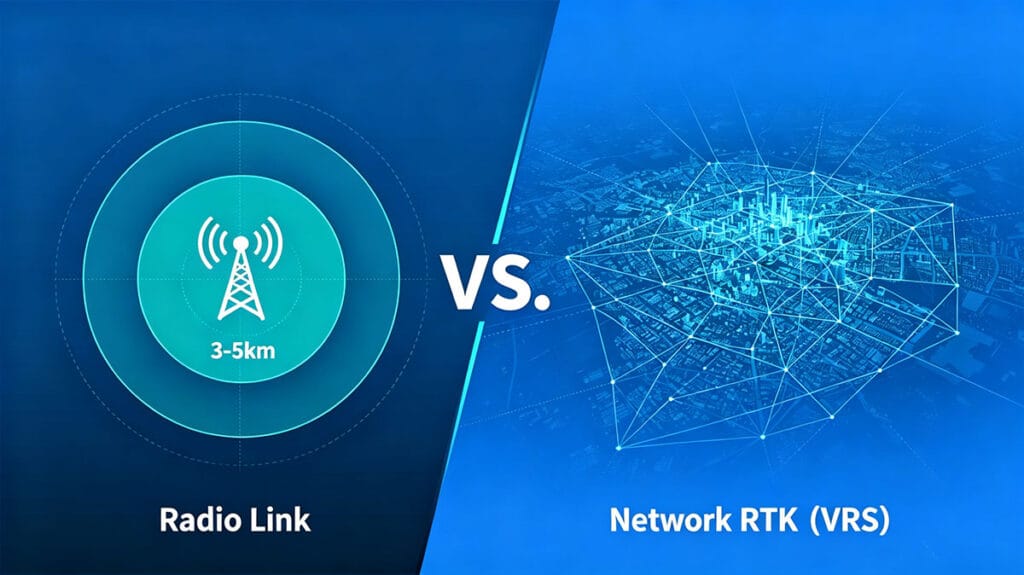
Reichweite von RTK-Basisstationen: Funkverbindung vs. Netzwerkverbindung – Was entspricht Ihren Anforderungen? 06.06.2026 Die Reichweite des Funks: RTK-Fähigkeiten über große Entfernungen Für Vermessungsingenieure und Kartografie-Experten ist die Reichweite der Basisstation ein entscheidender Faktor. Herkömmliche RTK-Konfigurationen basieren oft auf einer physischen Funkverbindung zwischen der Basisstation und dem Rover. Diese Methode bietet eine direkte, ortsgebundene und zuverlässige Verbindung, die unabhängig von Mobilfunknetzen ist. Ein gängiger Maßstab für einen robusten internen Funk ist eine Sichtreichweite von 3–5 km – eine Spezifikation, die für viele Feldanwendungen echtes Langstrecken-RTK definiert. Diese Fähigkeit ist unverzichtbar auf abgelegenen Baustellen, großflächigen landwirtschaftlichen Feldern oder unbebautem Gelände, wo keine Internetverbindung vorhanden ist. Der Reiz liegt in der Eigenständigkeit des Systems – sobald die Basisstation eingerichtet ist, schafft das System seine eigene Positionierungsblase und gewährt den Teams die Freiheit, innerhalb dieses Radius ohne externe Abhängigkeiten zu arbeiten. Es ist das klassische, bewährte Arbeitstier für hochpräzise Positionierung. Vergleich der Reichweite von RTK-Basisstationen: Langstrecken-RTK-Funk vs. Netzabdeckung Besprechen Sie Ihre Projektanforderungen Grenzen ausloten: Die RTK-Funkreichweite verstehen Die angegebene RTK-Funkreichweite, beispielsweise 3–5 km, entspricht einem idealen Szenario mit freier Sichtverbindung. In der Praxis wird diese Reichweite durch das Gelände, Hindernisse und die Antennenhöhe beeinflusst. Dichte städtische Umgebungen mit hohen Gebäuden oder stark bewaldete Gebiete können den effektiven Betriebsradius erheblich verringern. Die interne Funkleistung der Basisstation ist der entscheidende Faktor für diese Reichweite. Funkgeräte mit höherer Leistung können leichte Hindernisse besser durchdringen und auch am Rand der Nennreichweite eine stabile Datenverbindung aufrechterhalten. Für eine Marke wie TOKNAV, deren RTK-Empfänger T50Pro und T40Pro für anspruchsvolle Photogrammetrie- und Lasermessungen ausgelegt sind, gewährleistet eine starke, zuverlässige Funkverbindung, dass die Datenintegrität auch dann gewahrt bleibt, wenn sich die Rover von der Basisstation entfernen, wodurch kostspielige Nacharbeiten vermieden werden. Die innere Kraft: Die interne Funkleistung und ihre Rolle Die interne Funkleistung ist der stille Held eigenständiger RTK-Systeme. Sie bestimmt die Signalstärke und die Robustheit der von der Basisstation zum Rover übertragenen Daten. Ein Gerät mit robuster interner Funkleistung, wie die Modelle der RTK-Serie von TOKNAV, gewährleistet ein klareres Signal über größere Entfernungen und unter weniger als idealen Bedingungen. Dies wirkt sich direkt auf die Effizienz im Feld aus; Vermessungsingenieure können größere Flächen abdecken, ohne die Basisstation ständig versetzen zu müssen. Es handelt sich jedoch um eine lokal begrenzte Lösung. Die Funkreichweite bildet auf der Karte einen Kreis, in dessen Mittelpunkt die Basisstation steht. Bei Projekten, die diesen Kreis überschreiten – wie beispielsweise lineare Infrastrukturprojekte über Dutzende von Kilometern oder regionale Vermessungen –, ist es unpraktisch, sich ausschließlich auf Funk zu verlassen; dies erfordert mehrere Basisaufstellungen oder einen gänzlich anderen Ansatz. Der Vorteil des Netzwerks: Unbegrenzte Reichweite mit VRS/CORS Hier verändern Netzwerklösungen wie die Virtual Reference Station (VRS) oder die Continuously Operating Reference Stations (CORS) den RTK-Einsatz grundlegend. Anstelle einer einzelnen, vom Anwender aufgestellten Basisstation verbindet sich der Rover über mobiles Internet (4G/5G) mit einem Netzwerk aus permanenten, professionell gewarteten Referenzstationen. Dienste wie die VRS-Lösung von TOKNAV schaffen effektiv eine virtuelle Basisstation am Standort des Rovers und stellen Korrekturdaten über das Internet bereit. Die Reichweite wird nicht mehr durch eine 5-km-Funkblase definiert, sondern durch die Abdeckung des Mobilfunknetzes, die regional, national oder sogar kontinental sein kann. Dadurch entfällt die Notwendigkeit, eine eigene Basisstation einzurichten, die Reichweitenbeschränkung wird aufgehoben, und die Lösung eignet sich ideal für großflächige oder städtische Vermessungen. Angebot für Netzwerklösungen anfordern Reichweitenvergleich: 5-km-Funk vs. kontinentales Netz Vergleichen wir die Reichweitenmodelle direkt miteinander. Ein leistungsstarkes RTK-Funksystem bietet eine dedizierte, sichere Verbindung bis zu etwa 5 km. Seine Leistung ist konstant und wird von Mobilfunk-Funklöchern nicht beeinträchtigt, was es zum Spitzenreiter in abgelegenen Gebieten macht. Die Einschränkung ist rein geografischer Natur. Im Gegensatz dazu bietet eine Netzwerk-RTK-Verbindung theoretisch unbegrenzte Reichweite, wo immer Mobilfunkabdeckung vorhanden ist. Sie bietet unglaublichen Komfort für mobile Teams und Großprojekte. Der Nachteil ist die Abhängigkeit vom Mobilfunknetz und mögliche Abonnementgebühren für das Korrekturnetzwerk. Bei der Wahl geht es nicht darum, welche Technologie überlegen ist, sondern welche für die spezifische Projektumgebung, den Umfang und die logistischen Einschränkungen optimal ist. Die Wahl des richtigen Werkzeugs: Wann sollte man Funk- oder Netzwerk-RTK verwenden? Die Auswahl der richtigen Datenverbindung ist eine strategische Entscheidung. Verwenden Sie eine RTK-Funkverbindung mit großer Reichweite, wenn: ein Toknav-RTK-Empfänger mit Langstrecken-RTK-Funk im Einsatz ist – in abgelegenen Bergwerken, Steinbrüchen, auf Offshore-Anlagen oder auf ländlichen Feldern ohne Mobilfunkempfang; an gesicherten Standorten, an denen externe Datenverbindungen verboten sind; oder bei kurzfristigen, lokal begrenzten Projekten, bei denen die Einrichtung einer einzelnen Basisstation einfacher und kostengünstiger ist als die Verwaltung von Netzwerkabonnements. Entscheiden Sie sich für eine Netzwerk-RTK-Verbindung (VRS), wenn: Vermessungen über eine große Stadt oder einen langen, linearen Korridor wie eine Autobahn oder eine Pipeline durchgeführt werden; in Gebieten mit hervorragender Mobilfunkabdeckung gearbeitet wird; eine Flotte von Rovern über ein weitläufiges Gebiet hinweg verwaltet wird; oder wenn die operativen Effizienzgewinne durch den Verzicht auf eine physische Basisstation die Netzwerkkosten überwiegen. Das Toknav-Toolkit: Lösungen für jede Reichweitenanforderung Das Produktportfolio von TOKNAV ist strategisch darauf ausgelegt, beide Betriebsparadigmen zu unterstützen. Für traditionelles, funkbasiertes RTK mit großer Reichweite sind die Hochleistungsempfänger der Serie wie der T30 Pro (mit integrierter Photogrammetrie) und der T20Pro (multifunktionales intelligentes RTK) mit leistungsstarken internen Funkmodulen ausgestattet. Für Anwender, die ein eigenes CORS-Netzwerk aufbauen möchten, um Kontrolle und Abdeckung zu kombinieren, dient der NET660i-Basisstationsempfänger als robuste Grundlage. Für ein Höchstmaß an Reichweite und Komfort bietet die Nutzung der VRS-Lösung​ in Verbindung mit einem netzwerkfähigen Rover nahtlose, großflächige Präzision ohne Reichweitenangst – ideal für GIS-Fachleute, die Geräte wie den P8 Global verwenden. Flussdiagramm: So wählen Sie zwischen RTK-Funk und Netzwerk-RTK für Ihre Anforderungen an die Reichweite der Basisstation – Lassen Sie eine Reichweitenbewertung für Ihre Ausrüstung durchführen Das Fazit zur Reichweite von RTK-Basisstationen In der Debatte um die Reichweite von RTK-Funk und Netzwerk-RTK gibt es keinen universellen Sieger. Die 3–5 km lange Funkverbindung bietet eine zuverlässige, eigenständige Steuerung für definierte Standorte, die über die interne Funkleistung der Basiseinheit betrieben wird. Die Netzwerkverbindung, die auf VRS-Technologie basiert, bietet nahezu unbegrenzte RTK-Reichweite durch die Nutzung der Mobilfunkinfrastruktur und definiert damit neu, was RTK mit großer Reichweite wirklich bedeutet.In den fortschrittlichsten Betriebsabläufen wird häufig ein hybrider Ansatz verfolgt, bei dem Funk für kritische, signalfreie Standorte genutzt wird und bei Netzabdeckung auf den Netzwerkmodus umgeschaltet wird.

RTK-Basisstation Reichweite: Funk- vs. Netzwerkverbindung - was deckt Ihre Bedürfnisse ab? Weiterlesen »

Werden Sie TOKNAV-Vertriebspartner weltweit!

Mit einer bewährten Erfolgsbilanz in der Vermessungsbranche suchen wir jetzt nach leidenschaftlichen Vertriebsmitarbeitern, die an unserer globalen Erfolgsgeschichte teilhaben möchten.