
TOKNAV INSIGHTS
Shallow-Water Hydrographic Survey: Planning, USV Setup and Field Checks
Reviewed and updated October 21, 2026
A shallow-water survey is feasible only when the vessel, installed sensors and acquisition method can operate reliably in the same water envelope. A small published draft alone does not establish the minimum surveyable depth.
WATCH THE EQUIPMENT · EXPLORE THE RESULTS
Watch the planned survey become an on-water mission
These TBoat10-A and TBoat20-A demonstrations show task setup, survey lines, monitoring and processing. Apply the operating-envelope checks in this guide to your own waterway.
 ▶ 1:30
TBoat10-A · Field workflow
TBoat10-A Single-Beam Survey: Route Planning and Data Export
Watch TBoat10-A project setup, route planning, autonomous survey operation and the data-processing workflow in a TOKNAV field demonstration.
Watch video and read the steps →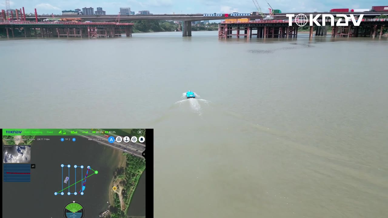 ▶ 2:20
TBoat20-A · Field workflow
TBoat20-A Single-Beam Survey: CORS, Survey Lines and Export
See TBoat20-A startup, project settings, CORS connection, survey-line planning, on-water operation and data export in a practical video.
Watch video and read the steps →This guide supports river, lake and reservoir planning. Use the hydrographic equipment and data-quality guide to select the wider survey workflow.
1. Define the required result and operating area
Map the boundary, launch and recovery points, expected depth range, current, vegetation, floating debris and obstructions. Establish the required coverage and output: line-based sections, a bathymetric surface or investigation of particular features. Document the applicable acceptance criteria and the method for handling unsurveyable areas.
Check conditions for the planned working period. A route that is accessible at one water level may become unsuitable as levels change. Keep the launch and recovery route within the assessed envelope.
2. Distinguish four depth-related limits
| Limit | What to establish |
|---|---|
| Loaded vessel draft | Immersion with the actual batteries, sensor payload and operating trim |
| Lowest installed component | The position of the transducer, mount, propulsion or other equipment below the surface |
| Sensor minimum usable range | The documented acoustic range and tested bottom tracking for the installed sounder |
| Operating clearance | The project allowance for bottom variability, motion, debris and changing water level |
Use a common reference for these measurements. For a downward-looking sounder, nominal transducer immersion plus minimum acoustic range provides only one screening limit; it is not an approved operating depth. The limiting component, required clearance and demonstrated data quality must also be considered.
3. Select sonar for the coverage requirement
A single-beam sounder collects depths along tracks. If gaps between tracks are acceptable, plan line spacing and check lines around the deliverable. Do not convert sampled lines into an unqualified full-coverage claim.
Multibeam covers a swath, but shallow depth can reduce the usable swath width and increase the number of lines needed. Base overlap and line spacing on the validated coverage at the site rather than a maximum advertised angle. Budget for motion, heading, sound-speed and alignment requirements.
Compare the options in the single-beam and multibeam selection guide. A boat's payload capacity alone does not prove that a particular sonar is integrated.
4. Prepare the loaded USV configuration
- Confirm payload mass, mounting rigidity, balance and adequate sensor immersion.
- Measure GNSS, motion-sensor and sonar offsets in the agreed coordinate convention.
- Verify timing and data interfaces; record configuration versions.
- Test the GNSS correction route along the planned working area, including near banks and structures.
- Confirm communications, operator control, recovery arrangements and the configured response to a lost link.
- Plan power for the actual payload and propulsion demand with a recovery reserve.
The TBoat10/TBoat20 comparison helps organize the platform questions. Request confirmation of the complete proposed package.
5. Run a representative pilot line
- Select a controlled test area representative of the working depth and bottom conditions.
- Verify positioning and the applicable draft, sound-speed and depth-reference checks.
- Acquire a short line at a conservative operating speed, recording raw sonar and navigation data.
- Inspect bottom tracking, time alignment, bubbles, vegetation returns and GNSS interruptions.
- Repeat or cross the line using the project check procedure.
- Confirm that the receiving software can reproduce the depth reduction and exports.
Approve the operating envelope only after reviewing the test results. If increasing speed degrades bottom tracking or produces aeration, reduce speed and investigate the mounting or flow conditions before resuming production.
6. Monitor quality and record exceptions
Track coverage, correction quality, sensor status and water-level changes throughout the mission. Mark the times and locations of suspect data. Stop and review when the system leaves its demonstrated operating envelope, bottom tracking becomes unreliable or recovery conditions deteriorate.
Do not classify vegetation tops or suspended returns as the bed without an appropriate interpretation method. Record inaccessible shallow margins as exclusions; select a separately validated complementary survey method if the contract requires those areas.
7. Hand over a traceable result
Retain raw sonar and navigation files, loaded configuration, sensor geometry, depth-reference inputs, test-line results and a coverage plot. Record quality flags, rejected observations and reacquired lines. Distinguish measured soundings from interpolation and report remaining gaps.
Review the hydrographic quality-control checklist before accepting the dataset.
Frequently asked questions
Can a shallow-draft USV survey in water equal to its draft?
No. Draft does not include a usable acoustic range or operational clearance. Evaluate the loaded installation and demonstrate reliable measurement at the intended depth.
Is single-beam always better in shallow water?
No. The coverage specification, depth range, bottom conditions and demonstrated sensor performance decide the method. Cost and processing requirements are part of that decision.
Check your shallow-water configuration
Send minimum depth, water-level variation, bottom conditions, launch access, required coverage and intended payload.
Discuss the operating envelope →